(fKICKER
MODEL:
Authorized KICKER Dealer:
Purchase Date:
Serial Number:
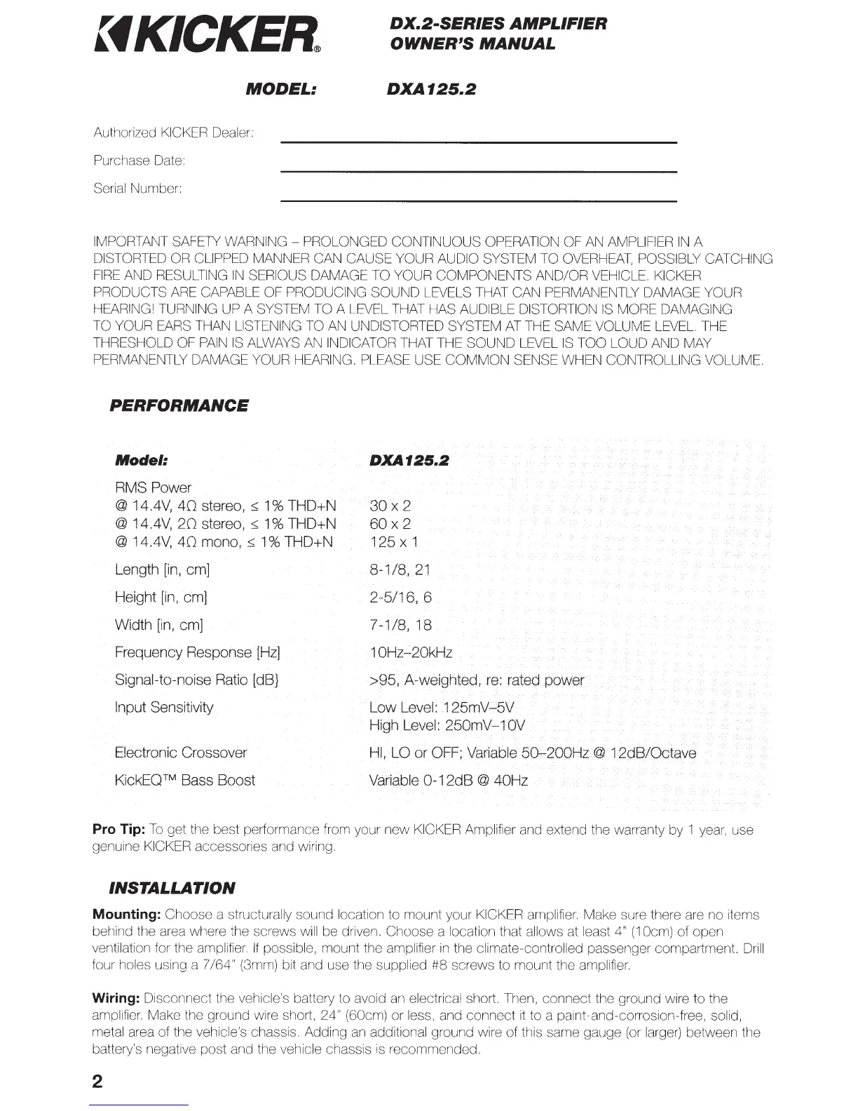
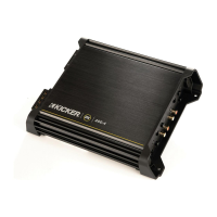
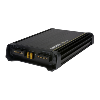
DX.2-SERIES
AMPLIFIER
OWNER'S
MANUAL
DXA125.2
IMPORTANT SAFE1Y
WARNING-
PROLONGED CONTINUOUS OPERATION OF AN AMPLIFIER
IN
A
DISTORTED OR CLIPPED MANNER CAN CAUSE YOUR AUDIO SYSTEM TO
OVERHEAT,
POSSIBLY CATCHING
FIRE
AND RESULTING
IN
SERIOUS DAMAGE TO YOUR COMPONENTS AND/OR VEHICLE. KICKER
PRODUCTS
ARE
CAPABLE OF PRODUCING SOUND LEVELS THAT CAN PERMANENTLY DAMAGE YOUR
HEARING! TURNING UP A SYSTEM TO A LEVEL THAT HAS AUDIBLE DISTORTION
IS
MORE DAMAGING
TO YOUR EARS THAN LISTENING TO
AN
UNDISTORTED SYSTEM
AT
THE SAME VOLUME
LEVEL.
THE
THRESHOLD OF
PAIN
IS
ALWAYS
AN
INDICATOR THAT THE SOUND LEVEL
IS
TOO LOUD AND MAY
PERMANENTLY DAMAGE YOUR HEARING. PLEASE USE
COMMON
SENSE WHEN CONTROLLING VOLUME.
PERFORMANCE
Model:
RMS Power
@ 14.4V,
40
stereo,
::;
1%
THD+N
@ 14.4V,
20
stereo,::;
1%
THD+N
@ 14.4V,
40
mono,~
1%
THD+N
Length
[in,
em]
Height
[in,
em]
Width
[in,
em]
Frequency Response
[Hz]
Signal-to-noise Ratio [dB}
Input Sensitivity
Electronic Crossover
KickEO ™ Bass Boost
DXA125.2
30x
2
60x
2
125 X 1
8-1/8,21
2-5/16, 6
7-1/8,
18
10Hz-20kHz
>95, A-weighted,
re:
rated power
Low Level: 125mV-5V
High Level: 250mV-1
OV
HI,
LO
or
OFF;
Variable
50-200Hz@
Variable
0-12dB
@ 40Hz
Pro Tip:
To
get the best performance from your
new
KICKER Amplifier and extend the warranty by 1
year,
use
genuine KICKER accessories and wiring.
INSTALLATION
Mounting: Choose a structurally sound location to mount your KICKER amplifier. Make sure there are no items
behind the area where the screws will be driven. Choose a location that allows at least 4"
(1
Ocm)
of open
ventilation for the amplifier.
If
possible, mount the amplifier
in
the climate-controlled passenger compartment. Drill
four holes using a 7
/64"
(3mm) bit and use the supplied
#8
screws to mount the amplifier.
Wiring: Disconnect the vehicle's battery to avoid an electrical short. Then, connect the ground wire to the
amplifier. Make the ground wire short, 24" (60cm) or less, and connect
it
to a paint-and-corrosion-free, solid,
metal area of the vehicle's chassis. Adding
an
additional ground wire of this same gauge
(or
larger) between the
battery's negative post and the vehicle chassis
is
recommended.
2