OR
2. If in Gross mode, press [NET/GROSS].
The [NET/GROSS] is an alternating action
key. If the scale is in the GROSS mode,
pressing the [NET/GROSS] key will place
it in the NET mode. If the scale is in the
NET mode, pressing the [NET/GROSS] will
place it in the GROSS mode.
If the “TARE” function has not been previ-
ously performed, the unit will stay in the Gross
mode and the message “FOR NET MODE
PRESS TARE” will scroll across the display.
NOTE: The scale is in the NET mode if there
is a flashing arrow pointing toward the NET
text just above the [TARE] key.
MODEL 150 - Optional Features:
Remote Display Options:
A Remote Display is available for viewing
weights at convenient locations. The Remote
Display includes a visual alarm light which
can be used with the TR4 option listed below.
TR/TR4 Options:
(Radio Control Operation) The TR and TR4
options allow the operator to remotely control
the scale from a distance up to 100 feet
away.
The TR option allows the operator to perform
TARE and GROSS functions.
The TR4 option allows remote operation of the
RM (recall memory), M+ (memory plus), TARE,
and either NET/GROSS or CM (clear memory).
Contact Digi-Star or your Digi-Star dealer
for additional options.
Indicator Mounting:
The indicator is easily attached directly to the
cart by securing the bottom with two (2) bolts,
size 1/4” x 3/4” and nuts. (See page 17 for
location.)
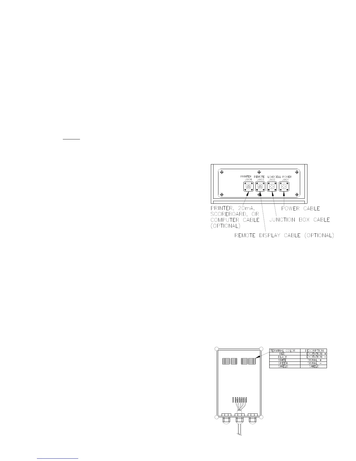
Power Connection:
The power cable should be connected directly
to a vehicle battery or regulated power supply.
The scale end of the power cable is attached
to the J901 connector located on the bottom
panel of the scale.
Connect the RED wire from the power cable
to +12 VDC and the BLACK wire to GROUND.
The indicator is fused internally at 10 amps.
POWER CABLE CONNECTIONS:
WIRE COLOR WIRE FUNCTIONS
RED Battery (+12 VDC)
BLACK GROUND
ORANGE Remote Alarm Out+
BLUE Remote Input
Remote Alarm Connection:
If a remote 12 VDC alarm is to be used,
connect the +12 VDC side of the alarm to
the power cable orange wire and the GROUND
side (or black wire) to the frame. The alarm
output is fused for a maximum drain of 10
amps. The remote alarm connection may also
be used for motor control purposes when used
with a relay.
SCALE BOTTOM PANEL
CABLE CONNECTIONS:
OM02488
Load Cell Connection:
The indicator is designed to operate with strain
gage load cells. The indicator will normally be
supplied with a “J-BOX” cable going between
the scale and the load cell junction box.
Extension Kits are available from your dealer
in various lengths.
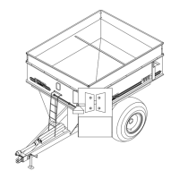
To connect the load cells, attach the junction
box cable to the J902 connector on the bot-
tom panel of the scale. Connect the load cell
cables to the junction box as shown below.
JUNCTION BOX LOAD CELL CABLE CON-
NECTIONS:
OM02489