OM02549
INSTALLATION OF OPTIONAL
HYDRAULIC DRIVE
The optional hydraulic drive unit eliminates
use of P.T.O. hook-up. Also available for this
kit is an optional anti-reversing kit and/or a
double Q/D set (refer to pg. 32.)
For fully operational hydraulic drive unit tractor
must:
-- be equipped with an optimum of a 30 G.P.M.
hydraulic system
-- have hydraulic hook-up of at least 4 ports.
*Refer to pg. 32 for illustration.
Assembly (Standard Kit)
1. Remove entire P.T.O. assembly and slip
clutch from cart. Hydraulic drive unit will
mount directly to the gear box.
2. Secure motor to mounting plate with 1/2”
hardware. Ports “A” and “B” should be on
the left side of plate to the inside of
motor bracket. (Determine right or left side
by looking in direction of forward travel.)
3. Attach universal joint to motor. After at-
taching the universal to the motor, slide
the opposite end of universal onto the
gearbox. Slide the universal and motor on
as far as it will go and secure universal
joint and motor. Position the mounting
bracket so that the universal is straight
and level to the gearbox.
4. Attach mounting plate to the mounting
bracket securing it with the 5/8” hardware
provided.
5. Attach male coupler in port “A” and male
elbow in port “B”. Attach swivel elbow to
male coupler.
6. Attach 84” hydraulic hose to each elbow.
7. At opposite end of hose attach a male
coupler. Attach a quick disconnect to each
end of the male couplers. Secure hoses,
and check for possible leaks.
Assembly (Anti-Reverse Kit)
1. Follow steps 1-4 in Standard Kit assem-
bly.
2. Connect 15” hydraulic hose to ends of
each elbow.
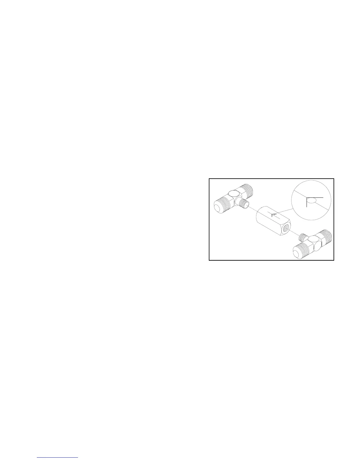
3. Before connecting tees to hose, assemble
anti-reverse valve and male tees as shown.
Note: Teflon tape or paste will be needed
on pipe threads. Once assembled connect
the 15” hoses making sure the arrow on
the valve is on top and pointing to the
left.
4. Connect 84” hydraulic hose to each male
tee.
5. At opposite end of hose attach a male
coupler. Attach a quick disconnect to each
end of the male couplers. Secure hoses,
and check for possible leaks.
8. Attach the “Caution” decal to the hydraulic
drive kit to show proper rotation of the
auger.