OM02557
Fig.5
ADJUSTABLE GEARBOX
OPERATION
Gearbox is pre-aligned at factory and welded,
centered on auger tube. Given time and wear,
gearbox may become out of alignment, caus-
ing excessive vibration and wear to the cart.
To correct this, follow these steps.
1. Break the two tack welds holding the plate
to the cart.
2. With tack welds broke, loosen the (4)
5/8” bolts. Be sure not to loosen them all
the way, auger may drop down, causing
total misalignment, or even injury.
3. With gearbox and plate free to move,
position auger so that it is center with
auger tube. Once centered, retighten bolts.
4. Clear work area and test run auger and
see that auger is centered with auger tube.
5. Once auger is set and centered with tube,
check tightness on bolts and tack weld
plate back into place. Run 2 tack welds
about 1” long on 2 sides of plate.
1
FRONT
2
3
4
5
6
6
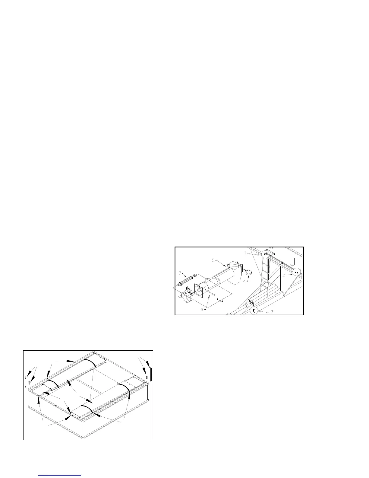
tom side of the cart for the flow control gate.
(3) U-brackets are welded along the inside
channel for protection of the hydraulic hoses.
Run the hoses between these brackets. (4)
Install work light to upper auger, securing it
to the brackets used for the upper bearing.
(5) Feed wire used for the light through the
channels welded to the backside of the upper
auger. (6) Install the upper auger so that it is
in the rest position, resting on the rest bracket
located to the back of the cart. Position au-
ger, lining up the holes where auger is hinged.
Once aligned secure hinge pin with expansion
pin. Refer to page 21 for hardware listing.
Auger screws will pre-align once upper auger
is extended. (7) Install hydraulic cylinder and
secure with cylinder pins and clips. The upper
auger or cylinder may have to be slightly
extended for proper alignment of cylinder pin
holes. Connect the cylinder hoses to the two
ports located below the lower auger tube.
Secure all hardware, wiring, and hydraulic
hoses and check for leaks.
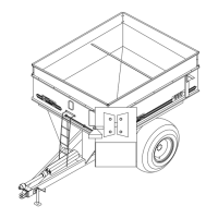
SIDEBOARDS
Refer to Fig. 4 for locations of each step.
The side boards should be assembled with
care so the paint does not get scratched. (1)
Cut the bands that hold the sideboards to-
gether. (2) Remove the mounting brackets on
the front of the cart. Do not remove side
mounting brackets until after end boards are
in place. Take note that the bolts used for
shipping should also be used for the final
mounting of the sideboards. (3) Stand the
end boards up one at a time using the center
bar on the cart and the cart sides for support.
Swing the end boards around into their final
mounting positions and put two bolts in them
to keep them in place. (4) Remove the side
mounting brackets, also saving these bolts.
(5) Lift the sideboards into place and bolt
them to the cart. (6) Take the corner brack-
Fig.4
ets out of the hardware bag tied to the frame
of the cart. Bolt the corner brackets on the
outside of the sideboards using the top set of
holes on each corner. Use the small corner
bracket on the inside of the sideboards. This
small bracket is reversible so it can be used
on all four corners. Bolt the small bracket on
the bottom set of holes on each corner mak-
ing sure that the bracket covers any gaps
that may exist in the corners. Before using
cart check that all bolts are in place and
tightened. Refer to page 28 for complete
hardware listings and final assembly illustra-
tion.
OM03187