AUGER SYSTEM
Annually check all bolts, nuts, and set screws.
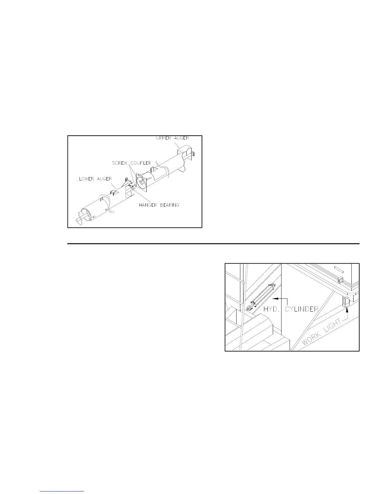
Perform lubrication as specified. The vertical
auger screw on upper and lower auger tubes
are designed to self align while extending upper
auger. (See fig. 2 for exact location.) If auger
is still misaligned, check the gear box to see
that all hardware is secure and tight. Follow
the instructions listed on page 18 for gear
box adjustment.
OM02525
FLOW CONTROL GATE
The Flow Control Gate is designed to prevent
grain form putting an excess load on the
horizontal auger during initial start-up. If gate
is not working properly check:
-- the hyd. cylinder, making sure hoses are
attached properly, clevis pins are secure, and
fluid level in cylinder is at its recommended
level.
-- for any debris that may have wedged be-
tween gate and auger tube.
-- Indicator rod. See that it is not binding up.
INDICATOR ARM
The Indicator Arm lets the operator know the
position of the flow control gate, open or
closed. This arm is connected to the flow
control gate. If the indicator arm is not work-
ing properly see that the hardware connecting
the indicator rod is secure with flow gate and
not binding up. See flow control gate for fur-
ther adjustments.
OM02556
Fig.3
Fig.2
ASSEMBLY
Some assembly is required before initial use
and operation. All Grain Carts are shipped
without the upper auger, work light, and hy-
draulic cylinder and hoses installed. The 690
model is shipped without the sideboards in-
stalled. If the dealer hasn’t already installed
all equipment, please refer to the following
guidelines for proper location and installation.
Before operation, double check to see that all
components are installed and working properly
to prevent damage to cart or personal injury.
All components of cart are shipped with cart
and stored in the least likely spot to be
damaged during shipping. All carts are shipped
with 1 upper auger, 1 work light, 1 hydraulic
cylinder, and 4 hydraulic hoses. The 690 Cart
is also shipped with 4 sideboards, 4 corner
braces, and 4 corner filler plates. The upper
auger is noticeable, located behind the ladder.
The hydraulic hoses are secured with cable
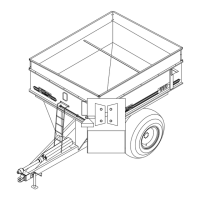
ties around the ladder. The hydraulic cylinder
is located on the right frame channel directly
behind front frame standard. The work light is
located, opposite the hydraulic cylinder, in a
box taped to the channel support. See Fig. 3
for locations.
The corner braces and filler plates are lo-
cated in a hardware bag on the frame oppo-
site the hyd. cylinder. The 690 sideboards
are shipped mounted flat on the top of the
cart.
INSTALLATION
Refer to (Fig. 5). Remove hydraulic hoses
from ladder by cutting the cable ties used in
shipping. Be careful not to cut hoses. On one
end of each hose is a hydraulic coupler that
will attach to the tractor. Connect the oppo-
site end to the cart. (1) Connect the two
male hoses to the female fittings used for the
upper auger. To prevent damage to these
hoses, secure to outside rail of ladder. (2)
The remaining 2 hoses will attach to the bolts