EasyManua.ls Logo

Kinco FV20-4T-0037G/0055L User Manual

Kinco FV20-4T-0037G/0055L
119 pages
To Next Page IconTo Next Page
Page #1 background imageLoading...
Page #1 background image
Preface
Thank you for using FV20 series Variable Frequency Drive made by Kinco Automation.
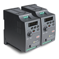
FV20 series inverter is a general-purpose high-performance vector inverter, which is mainly used to control
and adjust the speed and torque of three-phase AC asynchronous motor. It is a technical upgrade product of
FV100 series. FV20 adopts high-performance vector control technology, low speed and high torque output,
good dynamic characteristics, superior overload capability, those 45KW and below has built-in EMC filter
and brake unit, added user programmable function and background monitoring software. Support a variety of
PG cards, combined rich and powerful features, stable performance. It can be used in textile, paper, wire
drawing, machine tools, packaging, food, fans, pumps and various automated production equipment.
This manual provides information on model selection, parameters setting, trouble-shooting, and daily
maintenance. To ensure the correct installation and operation of FV20 series, please read this manual
carefully before starting the drive and keep it in a proper place and to the right person. Manufacturers should
follow the instructions in CN. and EN. version and Send it to the end-user for reference.
Precaution
To illustrate the details of the product, the illustrations in this manual are sometimes in the state of
removing the cover or safety cover. When using this product, be sure to install the cover or cover as
required and follow the instructions in the manual.
The illustrations in this manual are for illustrative purposes only and may differ from the products you
ordered.
The company is committed to continuous improvement of products, product features will be continuously
upgraded, and the information provided is subject to change without notice.
If you have any problems in use, please contact our regional agents or directly contact our customer
service center. Customer Service Phone 400-700-5281。

Table of Contents

Other manuals for Kinco FV20-4T-0037G/0055L

Questions and Answers:

Kinco FV20-4T-0037G/0055L Specifications

General IconGeneral
Power3.7kW/5.5kW
Control ModeV/F control
Communication InterfaceRS485
Operating Temperature-10°C to +40°C
Storage Temperature-20°C to +60°C
Protection FeaturesOvercurrent, overvoltage, undervoltage, overload, short circuit

Summary

Preface

Precaution

General safety and handling precautions for the FV20 series drive.

Quick Start Guide

Wiring

Details terminal connections for VFD power and I/O.

Common Setting Parameters

Lists common setting parameters with codes and descriptions.

Common Display Parameters

Lists common display parameters with codes and descriptions.

Chapter 1 Safety

1.1 Safety

General safety instructions and warnings for operating the drive.

1.2 Notes for Installations

Important installation precautions to prevent hazards.

1.3 Notes for Using FV20

Specific considerations for using the FV20 series drive.

1.3.1 About Motor and Load

How motor and load characteristics affect VFD operation.

1.3.2 About Variable Frequency Drive

Explains VFD behavior and precautions like PWM output.

1.4 Disposing Unwanted Driver

Guidelines for safe disposal of the VFD.

Chapter 2 Product Introduction

2.1 Nameplate introduction

Explanation of information found on the VFD's nameplate.

2.2 Model Description

Breakdown of the FV20 VFD model nomenclature.

2.3 General specifications

Key technical specifications of the FV20 series VFD.

2.4 Introduction of product series

Overview of the different models in the FV20 series.

2.5 Structure of VFD

Diagram showing the physical structure of the VFD.

2.6 External dimension and weight

Provides physical dimensions and weight information.

2.6.1 External dimension and weight

Detailed drawings of external dimensions and weight.

2.6.2 Operation panel and installation box

Dimensions for the operation panel and installation box.

2.7 Braking Resistor Selection

Guidance on selecting appropriate braking resistors.

Chapter 3 Installation Environment

3.1 Installation environment requirements

Specifies environmental conditions for VFD installation.

3.2 Inverter standard peripheral configuration

Diagram of typical peripheral devices connected to the inverter.

3.2.1 Configuring device description

Explains the function of each peripheral device.

Chapter 4 Wiring Guide of VFD

4.1 Wiring and Configuration of Main circuit terminal

Details on connecting main circuit power terminals.

4.1.1 Terminal Type of Main Loop’s Input and Output

Identifies main circuit terminal types for input and output.

4.1.2 Wiring of Main loop

Wiring diagrams for the main circuit loop.

4.1.3 Wiring of VFD for Basic Operation

Basic wiring chart for VFD operation.

4.2 Wiring and configuration of control circuit

Instructions for wiring the control circuit terminals.

4.2.1 Wiring of control circuit terminal.

Details on connecting control circuit terminals.

Chapter 5 Operation Instructions of Kinco VFD

5.1 Using Operation Panel

How to use the VFD's operation panel for setup and display.

5.1.1 Operation panel appearance and keys’ function description

Description of the panel layout and key functions.

5.1.2 Display status of operation panel

Explains how status parameters are displayed on the panel.

5.1.3 Panel Operation

Common examples of operations performed on the panel.

5.2 Operation mode of VFD

Describes the different control and operating modes of the VFD.

5.2.1 Control mode of VFD

Explains how the drive receives operating commands.

5.2.2 Operating Status

Details the three possible operating statuses of the VFD.

5.2.3 Control mode and operation mode of Kinco VFD

Discusses the VFD's three control methods: Vector/V/F.

5.2.4 The channels to set the VFD frequency

Describes the five operating modes for setting VFD frequency.

5.3 Power on the Drive for the first time

Steps for initial power-up and startup.

5.3.1 Checking before power on

Pre-power-on checks.

5.3.2 Operations when start up the first time

Detailed procedure for first-time startup.

Chapter 6 Parameter Introductions

6.1 Group A0

Introduction to basic operating parameters in Group A0.

6.2 Group A1

Introduction to start and stop parameters in Group A1.

6.3 Group A2

Introduction to skip frequency parameters in Group A2.

6.4 Group A3

Introduction to reference frequency curve parameters in Group A3.

6.5 Group A4

Introduction to Acc/Dec mode parameters in Group A4.

6.6 Group A5

Introduction to speed/torque control parameters in Group A5.

6.7 Group A6

Introduction to multi-function terminal parameters in Group A6.

6.8 Group A7

Introduction to PG parameters in Group A7.

6.9 Group A8

Introduction to fault parameters in Group A8.

6.10 Group b0

Introduction to motor parameters in Group b0.

6.11 Group b1

Introduction to V/F curve parameters in Group b1.

6.12 Group b2

Introduction to enhanced parameters in Group b2.

6.13 Group b3

Introduction to communication parameters in Group b3.

6.14 Group b4

Introduction to keyboard parameters in Group b4.

6.15 Group C0

Introduction to multi-section parameters in Group C0.

6.16 Group C1

Introduction to process PID parameters in Group C1.

6.17 Group C2

Introduction to simple PLC function parameters in Group C2.

Group C3: textile swing function

Introduction to textile swing function parameters in Group C3.

6.19 Group d0

Introduction to status display parameters in Group d0.

6.20 Group d1

Introduction to fault record parameters in Group d1.

6.21 Group d2

Introduction to product identity parameters in Group d2.

Chapter 7 Troubleshooting

Table 7-1 Faults and actions

Lists VFD faults and corresponding actions for troubleshooting.

Table 7-2 Abnormal phenomena and handling methods

Details common abnormal phenomena and their handling methods.

Chapter 8 Maintenance

8.1 Daily Maintenance

Routine daily checks for drive maintenance.

8.2 Periodical Maintenance

Recommended periodic maintenance schedule and checks.

8.3 Replacing Wearing Parts

Information on components that may need replacement and their lifespan.

8.4 Storage

Guidelines for storing the drive temporarily or long-term.

Chapter 9 List of Parameters

Table 9-1 Descriptions of Function Code Parameter Structure Table

Explains the structure and meaning of parameter tables.

Table 9-2 List of Parameters

Lists parameters by group, including name, unit, factory setting, and modification status.

Chapter 10 Communication Protocol

10.1 Networking Mode

Explains the two networking modes: master-slave.

10.2 Interfaces

Details the RS485 and RS232 interfaces.

10.3 Communication Modes

Discusses Modbus communication protocols and configurations.

10.4 Protocol Format

Shows the Modbus RTU and ASCII frame formats.

1). RTU mode

Explains the RTU mode communication protocol and examples.

2). ASCII mode

Explains the ASCII mode communication protocol and examples.

10.5 Protocol Function

Lists Modbus functions for parameter read/write operations.

10.6 Control parameters and status parameters of VFD

Overview of control and status parameters accessible via Modbus.

10.7 Some instructions

Important notes and instructions regarding parameter operations and saving.

10.8 Application example

Practical examples of Modbus communication for VFD control.

Chapter 11 Basic adjustment guide

11.1 Motor parameter self-tuning

Guide to performing motor parameter auto-tuning.

11.2 Start by Terminal, Frequency given by Analog

How to start the VFD using terminal control and analog frequency input.

11.3 Multi-speed operation

How to configure the VFD for multi-speed operation using terminals.

11.4 Communication mode controls the inverter

How to control the inverter via Modbus RTU communication.

Related product manuals