General Device Description
9119AA1_002-622e-02.15 Page 9
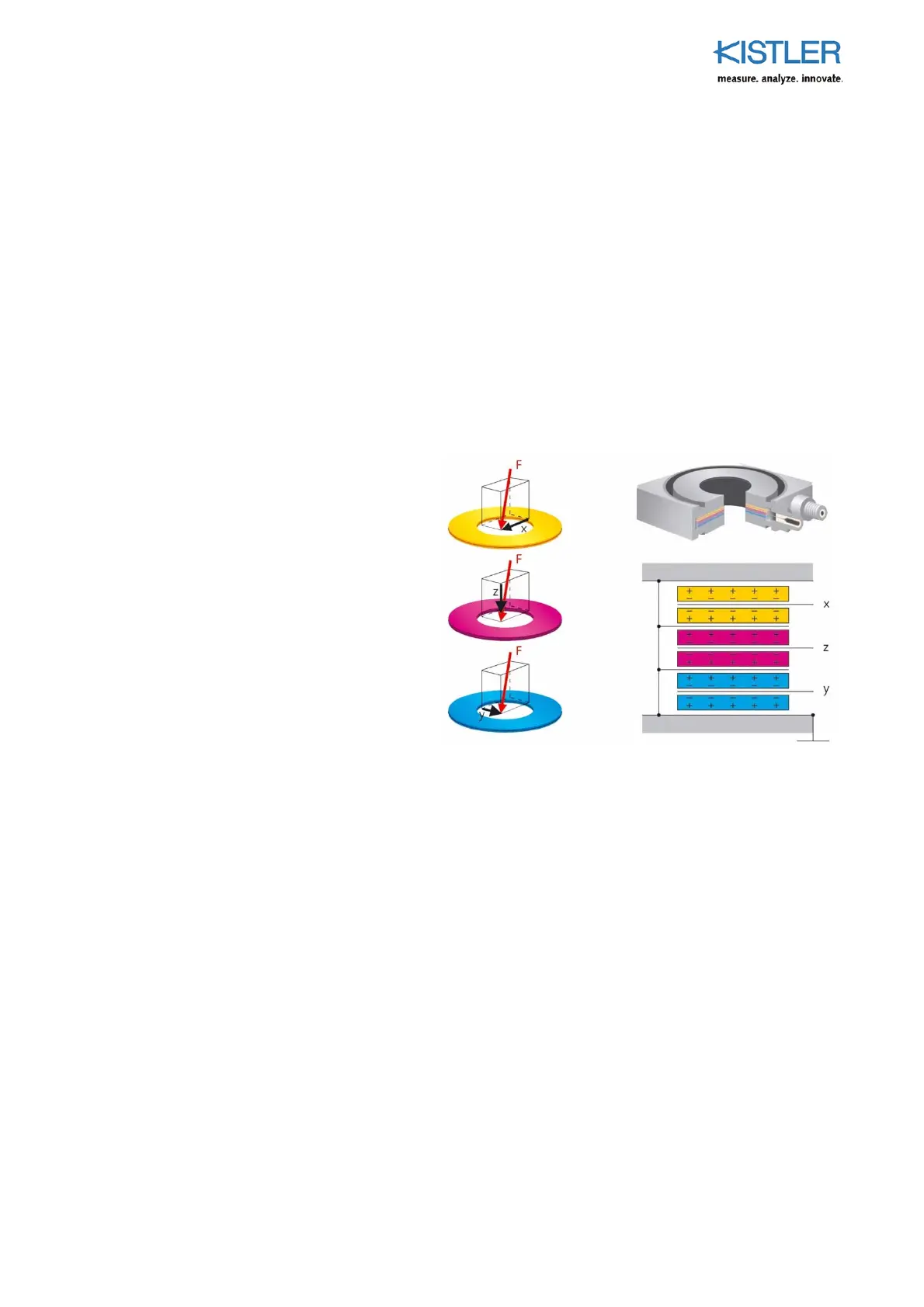
3.2 Functional Principle
The force to be measured is applied via a cover plate and
distributed to four, 3-component force sensors arranged
between the cover plate and the two base plates.
Each force sensor contains three quartz crystal plate pairs,
of which one is sensitive to pressure in the z direction and
the other two are sensitive to shear in the x and
y directions. There is practically no deflection during
measurement.
In these four force sensors, the applied force is split into
three components.
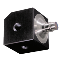
Fig. 2: Force sensor setup in the multicomponent
dynamometer: quartz crystal plate pairs for the 3
measuring directions
For force measurement with 3 components, the individual
signals are brought together in the connecting cable.
Positive or negative charges are produced at the
connections, depending on the direction of the force.
Negative charges produce positive voltages at the charge
amplifier output, and vice versa.
 Loading...