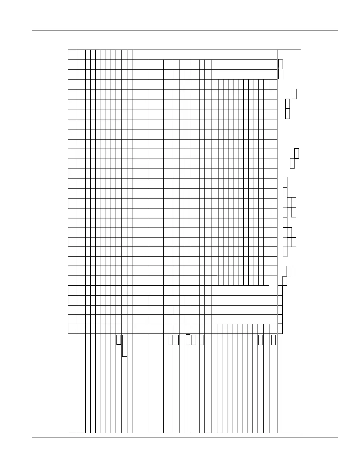
1 To invoke the Diagnostics Cycle, perform the following while in standby:
■ Press any 3 keys in the sequence 1-2-3-1-2-3-1-2-3 with no more
than 1 second between key presses.
■ The Service Diagnostics Cycle will start when the door is closed.
■ To rapid advance 1 interval at a time, press the Start/Resume key.
Rapid advance may skip sensor checks as some checks require
2 complete intervals.
NOTE: While you are in the Diagnostic Cycle, the Start/Resume feature is
turned Off (for example, Auto Resume after door interrupts) and the Start/
Resume key becomes an interval advance key.
■ Invoking Service Diagnostics Cycle clears all status and last run
information from memory and restores defaults. It also forces the
next cycle to be a sensor calibration cycle.
■
Drain and wash motors will pulsate on and off.
■ Last run cycles and options returned to default.
■ Last run Delay returns to the lowest delay increment.
■
Calibration cycle may force an extra rinse to occur prior to Final
Rinse (to assure clear water), then calibrates the OWI and the fill
amount during the final rinse.
■ Operating state returns to Standby upon completing or terminating
the Service Diagnostics Cycle.
2 Turn on all LEDs immediately upon receiving the entry sequence (even if
the door is open) for 5 seconds as a display test. Turn off all LEDs for
1 second prior to reporting customer error history.
3. Diverter will be on continuously in intervals 17 and 18. In all other diverter
intervals, diverter will be on only until it reaches the intended position for
that interval.
4 Press HI TEMP key in this interval to clear customer error history.
5 Thermistor (temperature sensor) checks - turn clean LED on if thermistor
is in its normal temperature range (32°F to 167°F [0°C to 75°C]). Turn
sanitized LED on if fill temperature is above 85°F (29°C).
6
OWI (optical soil sensor) checks:
■ Check OWI sensor for the presence of water during the 5-second
pause in interval 19 and turn on the Clean LED in interval 18 if water
detected.
■ Check OWI sensor for presence of bulk soil during pause interval
16 and turn on the Clean LED in interval 15 if bulk soil detected.
■ Drain until OWI sensor sees the presence of air or a maximum of
1:52 during interval 6 and turn on the Clean LED in interval 5 if air
detected.
7 Fan Motor on during upper rack washing intervals to reduce moisture
buildup in door.
8 Turn on Clean LED in this interval to indicate that vent current is detected.
9 Turn CLEAN LED on in this interval to indicate that the spray arm motor is
working (if present).
■
Lower spray arm (LSA) models are identified by the main lower spray
arm that does not freely rotate by hand.
■ Look for error code (F9E4) at end of service cycle for a faulty LSA
motor.
NOTE: Inoperable LSA motor will cause LSA sensor to indicate bad
status. See 9-4 error code table to diagnose.
10 Turn CLEAN LED on in this interval to indicate that the spray arm sensor
is working (if present).
■ Lower spray arm (LSA) models are identified by finger-shaped sensor
in tub, protruding from bottom left side of sump.
NOTE: Inoperable LSA motor will cause LSA sensor to indicate bad
status. See 9-4 error code table to diagnose.
11 Turn CLEAN LED on in this interval to indicate that the salt level reed
switch is closed.
 Loading...