2-5
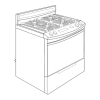
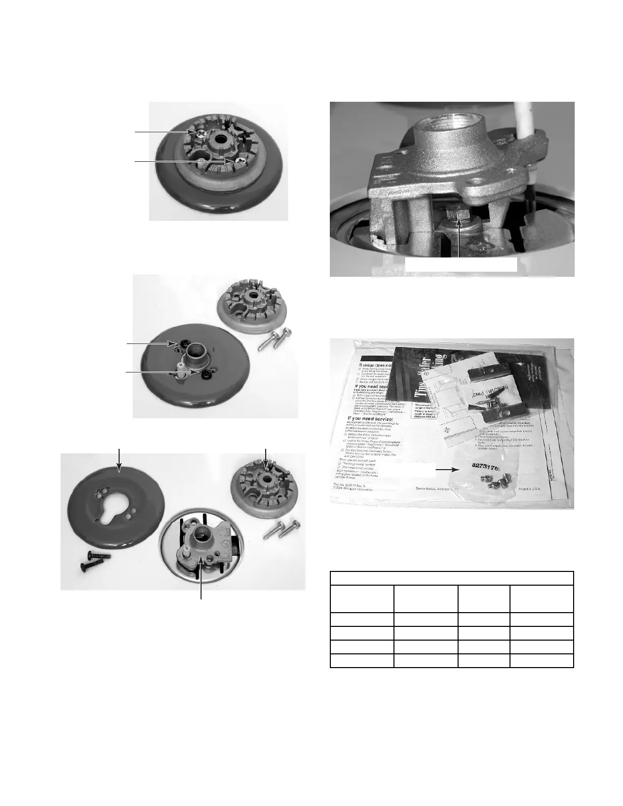
b)Remove the two screws from each of
the burner heads and lift the heads off
the cooktop.
d)Use an 8 mm socket and carefully re-
move the orifice spud from each of the
four burners.
f) Install the four L.P. gas orifices in the
burners, (do not overtighten them), as
shown in the following chart.
e)Remove the L.P. orifices from the small
plastic bag (located inside the literature
pack).
g)Place the natural gas orifices in the ori-
fice bag for possible later use.
Surface Propane Rate Orifice Color
Burner (B.T.U. /Hr) Number Marking
Left Rear 8,000 L80 Black
Left Front 11,000 L99 Green
Right Front 8,000 L80 Black
Right Rear 5,000 L65 Blue
L.P. GAS
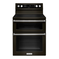
Burner Head
& Screws
Burner Head
Surface Burner
Decorative Cover
Decorative
Cover &
Screws
Orifice Bag
Surface Burner Orifice
c) If there is a decorative cover installed
around the burner, remove the screws,
and remove the cover.