1-10 CHAPTER 1 Overview
Series 3000 Sonar System Operations and Maintenance Manual 11210066, Rev. 11
The data from the towfish arrives in serial NRZ format and is conditioned and
input to the clock recovery circuit. The recovered clock is used to strobe the
serial data into a line decoder. The decoded data is converted to parallel format
and output the front panel connector.
The downlink modulator is used to indicate to the towfish when to fire the
main array and to send commands to the towfish. The modulator uses FSK
modulation and is frequency multiplexed before being amplified and combined
with 200-volt power which is then transmitted down the tow cable. The CPU
board controls the modulator.
Front panel. The power switch is located on the front panel as shown in
Figure 1-1 on page 1-3. All control of the TPU is done remotely via the LAN.
Power supply. The power supply provides 200 VDC to energize the towfish
via the tow cable and to generate ±12 VDC and +5 VDC power to energize the
sonar transceiver electronics.
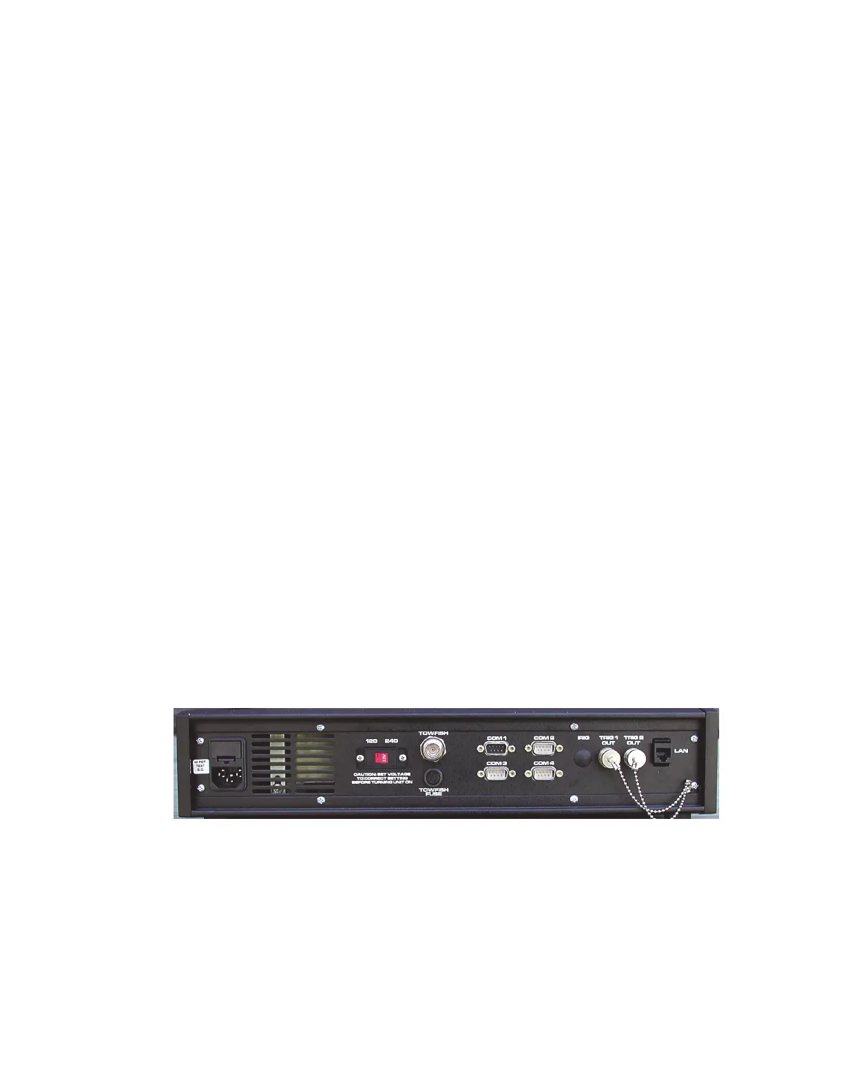
Rear connector panel. The rear connector panel provides the following I/O
connectors as shown in Figure 1-6:
• TOWFISH (See also Table 1-2.)
• AC (See also Table 1-3.)
• COM 1, COM 2, COM 3, and COM 2 (See also Table 1-4.)
• TRIG IN/IRIG (optional)
• TRIG 1 OUT
• TRIG 2 OUT
•LAN
Figure 1-6: TPU Rear Panel
 Loading...