CSC-3000 Series Pneumatic VAV Reset Volume Controllers 8 Applications Guide, Rev G
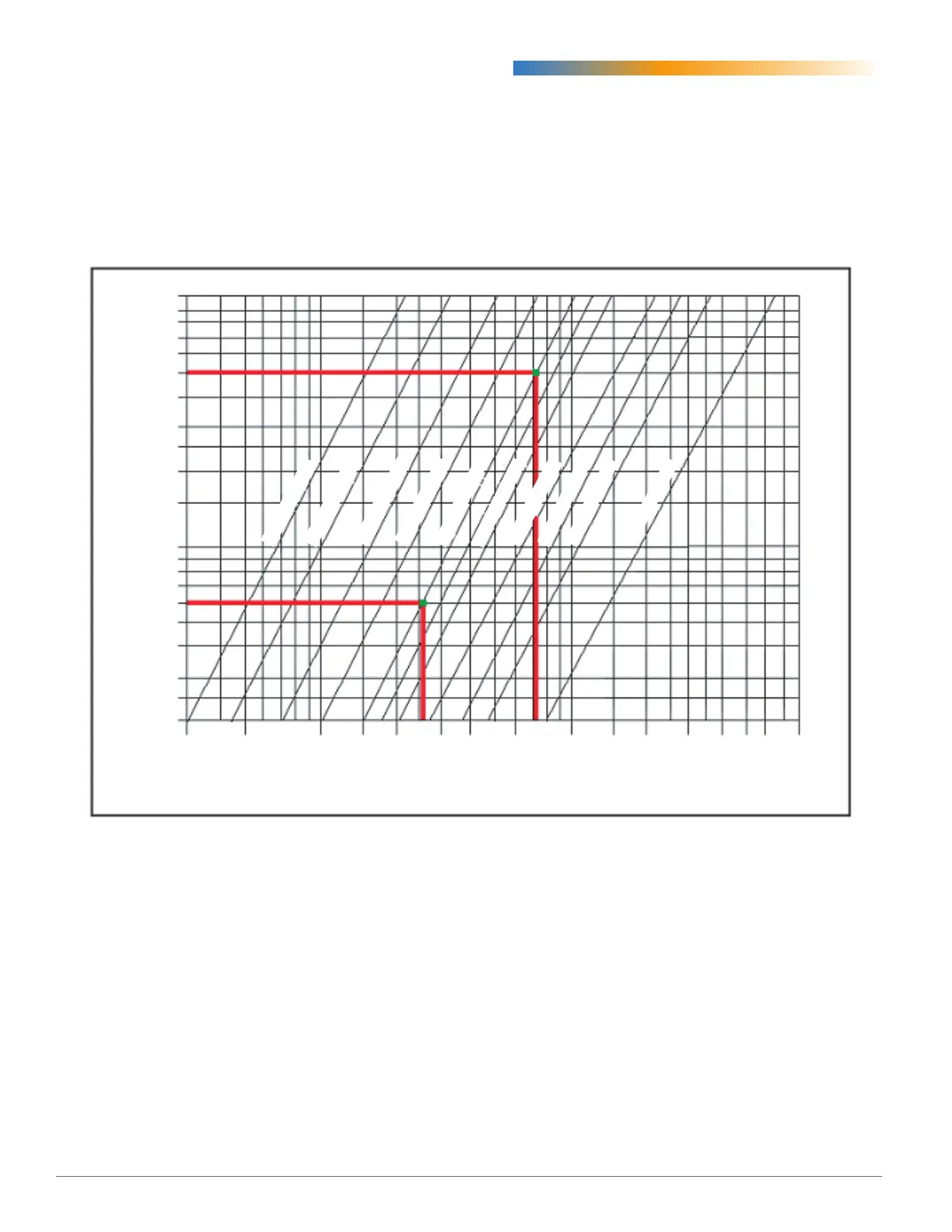
Magnehelic Gauge to Airflow Rate Chart
VAV Airow Rate by Duct Size
30 50 100 150 200 300 400 600 1000 1500 2000 3000 4000 6000 8000
4 inch Round
5 inch Round
6 inch Round
8 inch Round
14 inch Oval
12 inch Round
10 inch Round
16 inch Oval
18 inch Oval
20 inch Oval
.02
.03
.04
.05
.06
.07
.08
.09
.10
.15
.20
.25
.30
.40
.50
.80
.70
.60
1.0
.90
CFM Flow Rate as read by sensor
Differential Pressure (∆P) in Inches w.c.
NOTE: This chart is for illustration only! Do not
use this chart to obtain your values.It
isNOTintendedforcalibrationofyour
MinimumandMaximumadjustments.
Thisairowchartisanexampleofthechartsusually
axedtotheVAVbox.Eachchartisspecicforthe
typeofowsensorlocatedintheinletsideoftheVAV
box.ReadthedierentialpressureoftheMagnehelic
gauge,followthelinehorizontallyuntilitcrossesthe
diagonalinletsizeofbox.Readstraightdownfrom
thisintersectiontodeterminetheowrate.

 Loading...