Operating manual Energy storage solutions
V1.3DE/EN
21
5
Commissioning
English
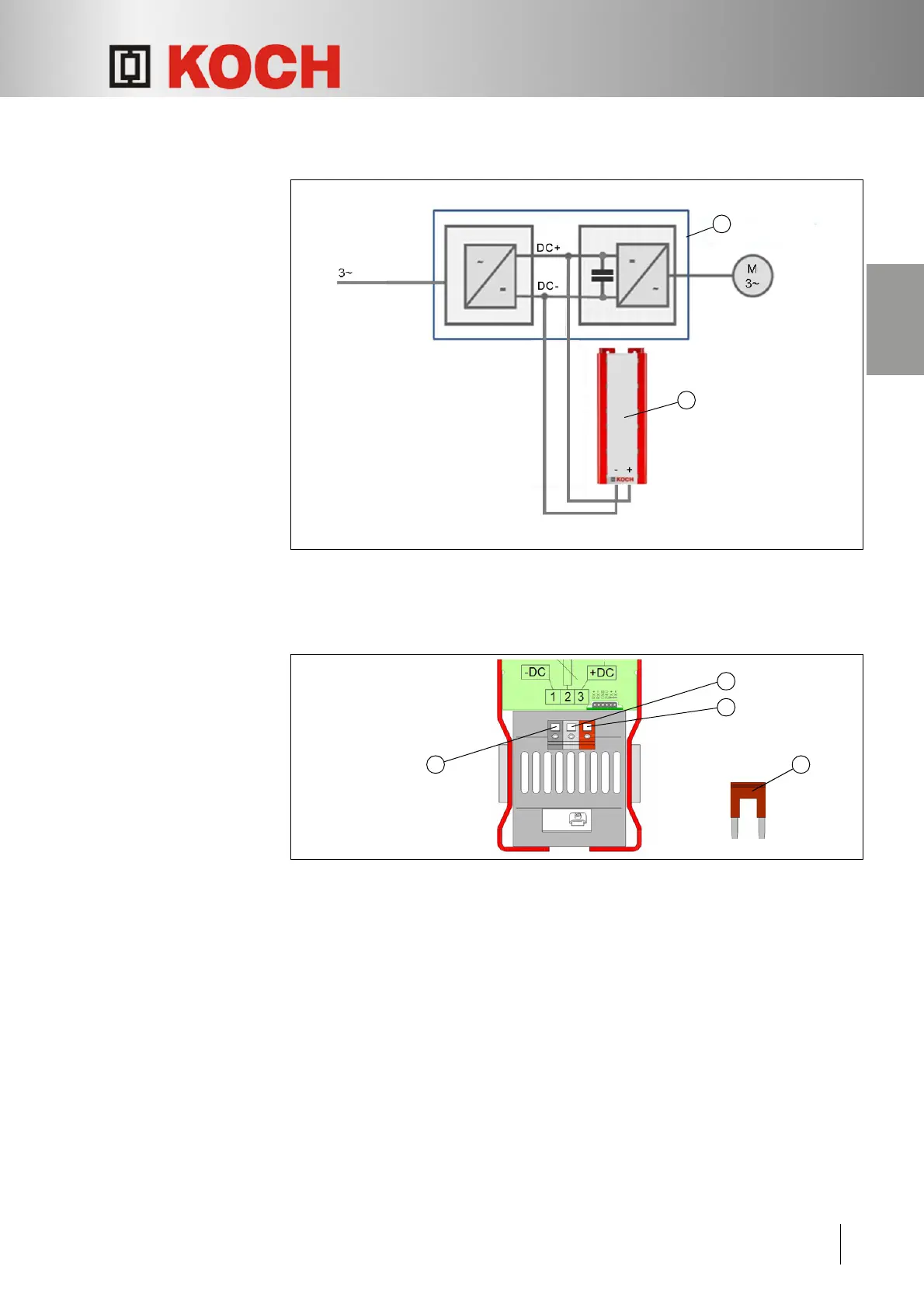
5.1.2 Connecting the DEV, KEV
Fig. 8: Connection diagram
1 Application
2 Energy storage solution (DEV, KEV)
The commissioning
procedure
Fig. 9: Connecting terminals on the bottom of the housing
Determine the polarity of the DC link connections.
De-energise the DC link.
Make sure that there is no voltage on the DC link.
Remove the discharge bridge r between "–DC" q (black terminal) and "BR" w
(grey terminal).
Make sure that there is no voltage between "–DC" q (black terminal) and "+DC" e
(red terminal).
Connect the negative pole of the application's DC link output with
"–DC" q (black terminal) on the Energy storage solution.
Connect the positive pole of the application's DC link output with
"+DC" e (red terminal) on the Energy storage solution.
 Loading...