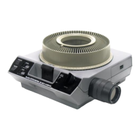
S
LIDE
IDENTIFICATION
NUMBERS
FIGURE
6
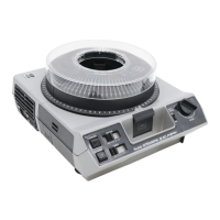
FIGURE
7
bottom plate until the index hole points to the index notch.
Then release the latch.
The molded numbers
on
the trays are
SLIDE
IDENTIFICATION
NUMBERS
(Figure 6) . (Only even numbers are marked
on
the
140 tray.) The slide being shown will
be
opposite the gate
index
on
the projector.
Remove the slide
LOCK
RING
(Figure 6)
by
turning
it
counterclockwise (UNLOCK) and
lifting
it
off the tray. Insert
a slide
in
each slot
in
the tray, orienting the slide so
that
the
image projected
on
the screen
is
right side up and reads
correctly from left
to
right.
After
all slides are in the tray, replace the lock ring,
turn·
ing
it
toward
LOCK
until you feel the detent action once or
twice. This will lock the ring
to
the tray.
INSTALLING THE SLIDE
TRAY
The
CAROUSEL
Universal and
CAROUSEL
Trays
Hold the tray over the projector, center
it
over the center
post
on
the top of the projector, and
turn
it to place the
slide· identification number
"O"-or
"zero
position"-at
the
GATE
INDEX,
as
shown
in
Figure 7. Next, lower the tray and
seat
it
firmly
within the
SLIDE
TRAY
GUIDE
RING
.
If
the tray and
projector components do not mesh properly, recheck the
metal slide retainer plate
as
described under
"Loading
the
Slide Tray. "
The
CAROUSEL
140
Tray
Put the loaded slide tray
on
the projector so
that
the hole
in
the center of the tray fits over the center post
on
the top
of the projector; then revolve the
tray
slowly in a clockwise
direction
until the identification
bar-or
"zero
position"-
(between numbers 2 and 140)
on
the tray is adjacent
to
the
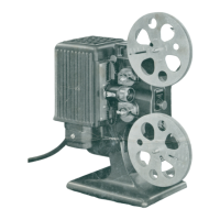
6
POWER CORD
CORD
COMPARTMENT
FIGURE
8
gate index. The tray will drop into operating position
on
the
top of the projector.
If
the slide
tray
does not easily drop
into place, check the alignment of the index hole and index
notch
as
described
under"
Loading the Slide
Tray."
NOTE: The
140
tray
drops down farther
during
the
first
change cycle or when the select button is pressed.
Using an Extra Slide
or
Cardboard
If
you wish to use
an
extra slide,
for
a total of 81 (or 141
with the
140
tray), or a
title
slide
that
will
be
projected
as
soon
as
the projection lamp goes on, insert
this
slide in the
projector gate (see Figure 10) before you set the tray in
place. Or,
if
you want the screen
to
be
dark
after
you have
shown slide No.
80
(or No.
140
in the
140
tray), insert a
2 x 2·inch piece
of
thin
cardboard in the gate before you
position the tray
on
the projector. This additional slide
or
piece of cardboard will enter the blocked·off space in the
tray at No. 0 when the first regular slide is projected;
it
will
return
to
the gate when the slide
tray
is positioned at zero.
Another use
for
the 2 x 2·inch cardboard
is
to
separate
or terminate small groups of slides in a tray. Insert a card·
board in the
tray
whenever you want a dark·screen interval.
PREPARING THE
PROJECTOR
1. Open the door of the
CORD
COMPARTMENT
(Figure 8)
on
the
bottom of the projector. Remove the remote control cord
and withdraw the
POWER
CORD
.
IMPORTANT: Always make sure you have pulled out the
cord
to
its full length before you
turn
on
the projector.
The
compartment
must
not
be
used
for
storage
during
projection
. This is necessary to provide proper
air
circula·
tion through the projector case.

 Loading...