54 TP-7092 11/22
3.15 ATS Status Menu
ATS menus appear if a Model RXT transfer switch is connected to the generator set. If no transfer switch is connected, or
another model ATS is connected to the engine start connections, Remote ATS is displayed on the ATS Status screen.
The ATS Status menu displays Model RXT transfer switch and source information.
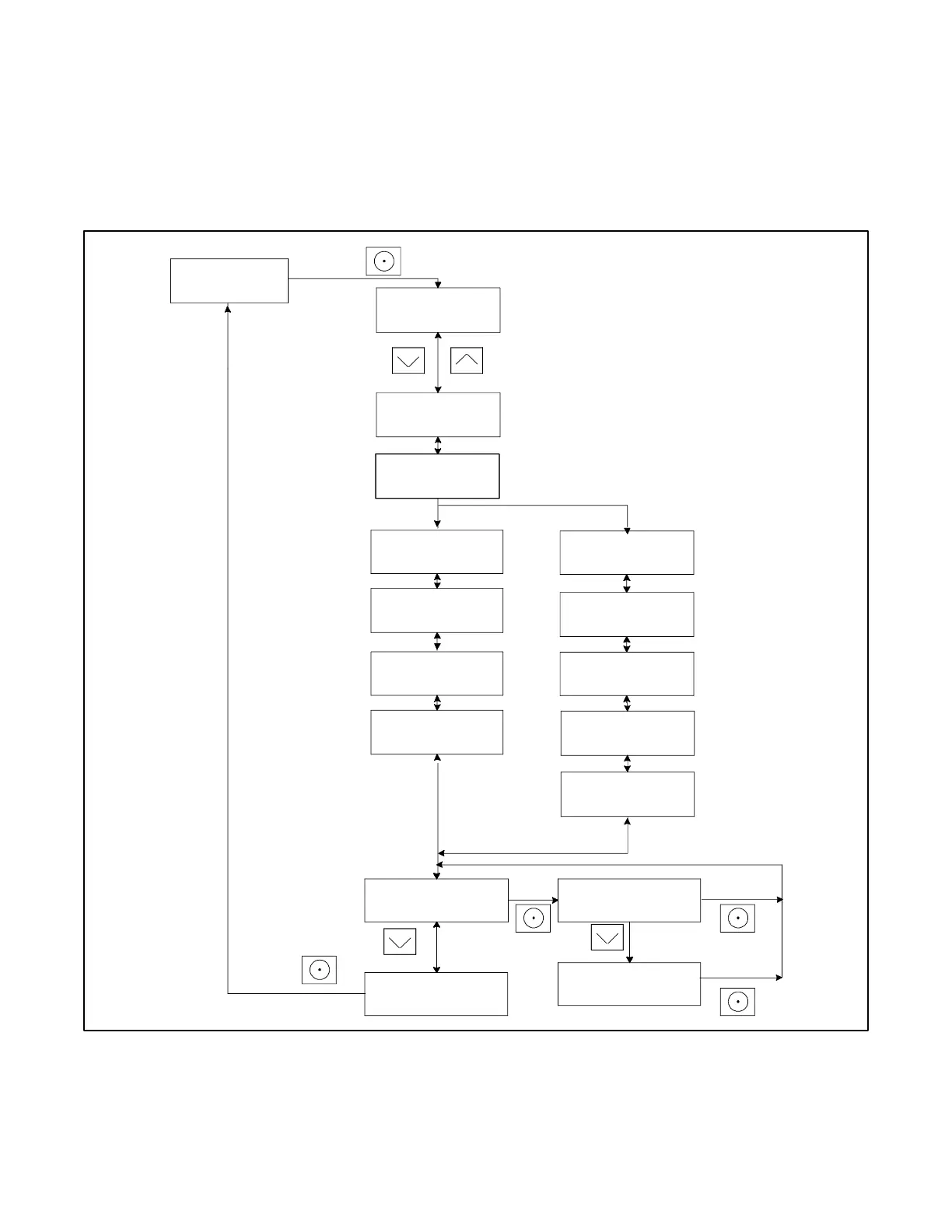
The voltage shown in these menus can be calibrated. Follow the safety precautions at the beginning of this manuals. Use a
voltmeter to measure the line-to-line voltage and follow the instructions in Figure 43 to calibrate the voltage readings.
Figure 43 ATS Status Menu, with Calibration
Note:
If there is no Model RXT transfer switch connected to the
generator set, Remote ATS is displayed and the other
screens on this page do not appear.