22 TP-7203 4/23
2.1 Electrical Connections
Several electrical connections must be made between the generator set and other components of the system for proper
operation. Most field-installed accessory kits include installation instructions. Comply with applicable national and local codes
when installing a wiring system.
For Canadian installations, refer to the Canadian Electrical Code (CEC).
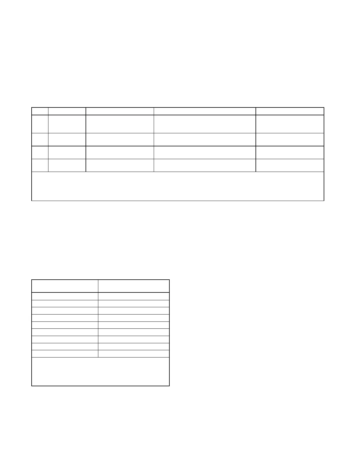
For customer-supplied wiring, select the wire temperature rating in Figure 7 based upon the following criteria:
• Select row 1, 2, 3, or 4 if the circuit rating is 110 amperes or less or requires #1 AWG (42.4 mm
2
) or smaller conductors.
• Select row 3 or 4 if the circuit rating is greater than 110 amperes or requires #1 AWG (42.4 mm
2
) or larger conductors.
Cu/Aluminum (Al) Combinations
60˚C (140˚F)
Or
75˚C (167˚F)
Use No. * AWG, 60˚C wire or
use No. * AWG, 75˚C wire
Use 60˚C wire, either No. * AWG Cu, or No. *
AWG Al or use 75˚C wire, either No. * AWG
Cu or No. * AWG Al
Use 60˚C wire, No.* AWG or
use 75˚C wire, No. * AWG
Use 60˚C wire, either No. * AWG Cu or No. *
AWG Al
Use No. *† AWG, 75˚C wire
Use 75˚C wire, either No. *† AWG Cu or No.
*† AWG Al
Use 75˚C wire, No.* † AWG
Use No. *† AWG, 90˚C wire
Use 90˚C wire, either No. *† AWG Cu or No.
*† AWG Al
Use 90˚C wire, No.* † AWG
* The wire size for 60˚C (140˚F) wire is not required to be included in the marking. If included, the wire size is based on ampacities for the
wire given in Table 310-16 of the National Electrical Code
®
, in ANSI/NFPA 70, and on 115% of the maximum current that the circuit carries
under rated conditions. The National Electrical Code
®
, is a registered trademark of the National Fire Protection Association, Inc.
† Use the larger of the following conductors: the same size conductor as that used for the temperature test or one selected using the
guidelines in the preceding footnote.
Figure 7 Terminal Markings for Various Temperature Ratings and Conductors
2.2 Terminal Connector Torque
Use the torque values shown in Figure 8 or Figure 9 for terminal connectors. Refer to UL-486A, UL-486B, and UL-486E for
information on terminal connectors for aluminum and/or copper conductors. Comply with applicable national, state, and local
codes when installing a wiring system.
Note:
If a connector has a clamp screw such as a slotted, hexagonal head screw with more than one means of tightening, test the
connector using both applicable torque values provided in Figure 9.
Socket Size Across Flats,
mm (in.)
Tightening Torque,
Nm (in. lb.)
Note:
For values of slot width or length not corresponding to those
specified, select the largest torque value associated with the
conductor size. Slot width is the nominal design value. Slot
length is to be measured at the bottom of the slot.
Figure 8 Tightening Torque for Pressure Wire Connectors with Internal-Drive Socket-Head Screws
 Loading...