30 TP-7203 4/23
2.8 Communication Cable Specifications
The following sections cover communication connections from the generator set to automatic transfer switches and RBUS
accessories, including the programmable interface module (PIM) and the load shed kit.
RBUS Connections A and B
For the RBUS communication connections A and B to the optional RBUS modules, use 20 AWG shielded, twisted-pair
communication cable. Belden #9402 (two-pair) or Belden #8762 (single-pair) or equivalent cable is recommended. Optional
RBUS modules can include the Model RXT transfer switch, RXT combined interface/load management board, automatic
paralleling module (APM), programmable interface module (PIM), and/or the load shed kit for the RDT or RXT transfer switch.
For outdoor installations, including those with buried cables and or conduit, use outdoor- rated Belden #1075A or equivalent
20 AWG shielded, twisted-pair communication cable.
PWR and COM Connections
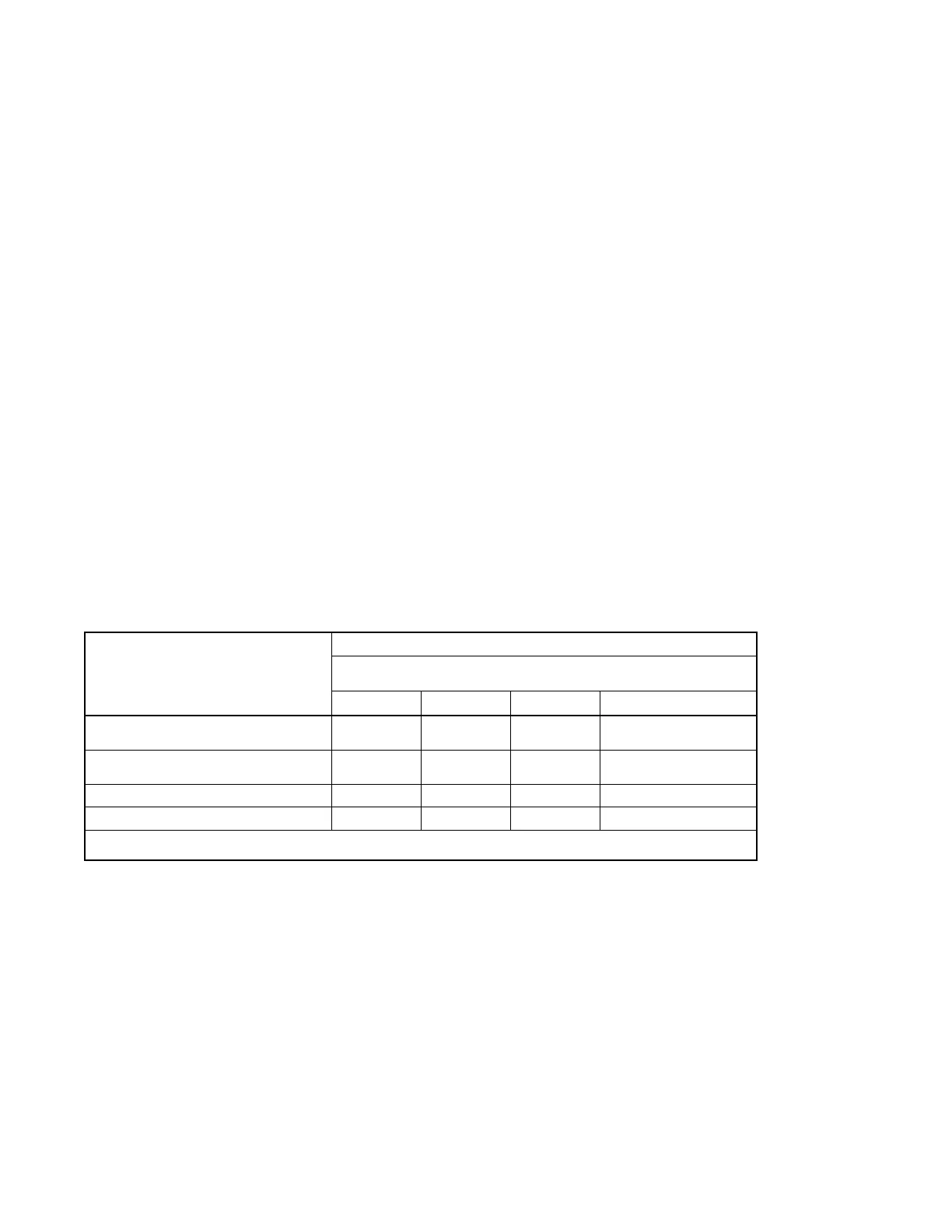
For the PWR and COM connections, the cable size and maximum cable length depends on the number of modules connected.
See Figure 15. Note the shield connections shown in the Accessory Module Communication Connection Details figure.
• For short cable runs shown in the first two rows of Figure 15, use one pair in the two-pair communication cable for the
A and B connections, and use the second pair for the PWR and COM connections.
• For the longer cable runs shown in the last two rows of Figure 15, use 12 or 14 AWG cable for PWR and COM, and
use the 20 AWG communication cable specified above for the A and B connections only. In this case, single-pair
communication cable such as Belden #8762 can be used for the A and B connections.
Note:
A model RXT transfer switch with combined interface/load management board acts as two RBUS modules: one RXT transfer
switch and one load management device.
Note:
Power relay modules, if used, are not RBUS modules and do not have RBUS communication connections.
 Loading...