TP-7203 4/23 53
6.7 Programmable Interface Module (PIM)
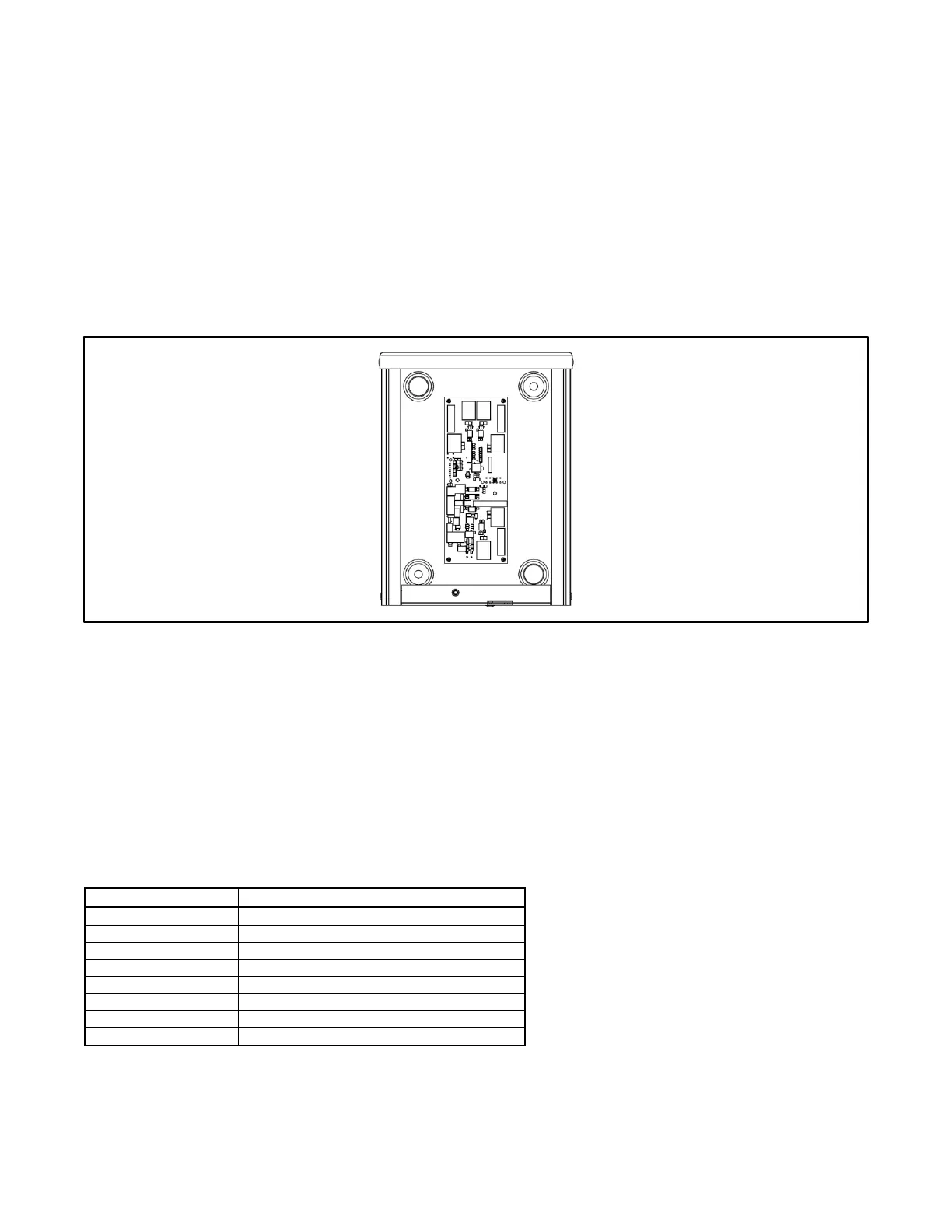
The optional Programmable Interface Module (PIM) provides two programmable inputs and six dry contact outputs, four of which
are programmable. The PIM with enclosure is shown in the Programmable Interface Module (PIM) figure (covered removed for
illustration). See TT-1584 for PIM installation and connection instructions.
The PIM is mounted in a NEMA 3R aluminum enclosure, which can be mounted indoors or outdoors. See the Accessory
Module RBUS Communication Connections section and the installation instructions provided with the PIM for the maximum
recommended cable lengths and detailed installation instructions.
6.7.1 PIM to Generator Set Connections
The PIM communicates with the RDC2 generator set controller. Connect the PIM module to the generator set as shown in the
Accessory Module RBUS Communication Connections section.
Figure 36 Programmable Interface Module (PIM) (covered removed for illustration)
6.7.2 PIM Inputs and Outputs
Connect customer-supplied equipment to the PIM as instructed in TT-1584.
Factory-default settings for the outputs are shown in Figure 37. The outputs are controlled by the RDC2 controller. The run
output is activated when the generator set is running. The common fault output is activated on a fault.
Use a personal computer running Kohler
®
OnCue
®
Plus or SiteTech™ software to assign functions to the other inputs and
outputs, and/or change the settings for factory-set inputs and outputs. Verify that the input and output assignments match the
connections to the PIM terminal strip.
Outputs 3 through 6 can also be controlled remotely using the OnCue
®
Plus program. If an output is activated or deactivated
through OnCue Plus, it is no longer controlled by the RDC2 controller. See the OnCue Plus Manual for instructions.
 Loading...