TP-5982 4/06 15Section 3 Cooling System
Section 3 Cooling System
3.1 Ventilation
Engine combustion, generator cooling, and expulsion of
flammable and lethal fumes require ventilation. Provide
ventilation compliant with USCG regulations governing
the sizing of vents and other considerations.
As a rule, size each inlet- and outlet-vent area to a
minimum of 13 sq. cm/30.5 cm (2 sq. in. per ft.) of the
craft’s beam. Should this rule conflict with USCG
regulations, follow USCG regulations. For applications
with screened inlets, double the size of the hull/deck
openings. Extend the vent ducts to bilges to expel
heavier-than-air fumes.
For generator sets mounted in the engine compartment,
increase the air flow to allow for the generator set’s
requirements. Install UL-listed, ignition-protected
blowers in the outlet vents and wire them to operate
before starting the engine(s). Install optional detection
devices to cause alarm, warning, or engine shutdown
should dangerous fumes accumulate in the
compartment.
Explosion.
Gasoline vapors can cause
explosion and severe injury or
death.
Before starting the generator set,
operate the blower 4 minutes and
check the engine compartment for
gasoline vapors.
WARNING
See the current generator set specification sheet for air
requirements. The air intake silencer/cleaner provides
combustion air to the engine. Do not compromise the
recommended minimum clearance of 38 mm (1.5 in.)
between a duct opening and enclosure wall. The
engine/generator performance will be adversely
affected if the installer neglects these guidelines. Follow
these guidelines to optimize generator set performance.
See Figure 3-1 for allowable intake restriction.
Note: ISO 3046 derates apply. See Appendix C.
Model Normal Intake Restriction*
5/7.3E and 4/6EF
5/7.3ECD and 4/6EFCD
.
ps
.7
n.
2
10/13/15EG and 13/15EGZ 0.36 psi (10 in. H
2
O)
15/20C and 12.5/16CF 0.01 psi (0.29 in. H
2
O)
* Clean backfire flame arrestor.
Figure 3-1 Intake Restriction
3.2 Cooling System Components
Design the marine generator set cooling system to
include the following features.
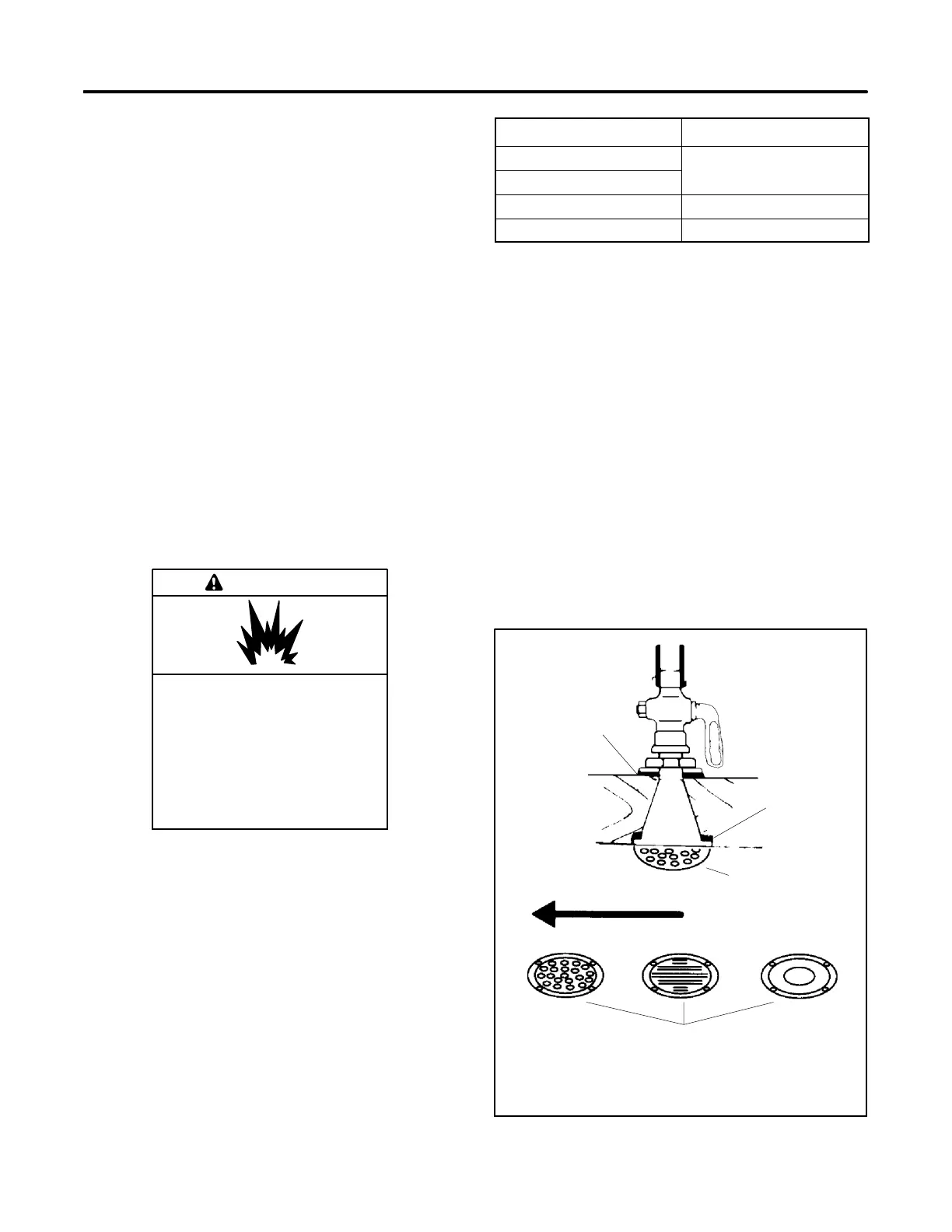
3.2.1 Intake Through-Hull Strainer
(Seacock Cover)
Install a screened intake through-hull strainer to prevent
entry of foreign objects. Use perforated, slotted-hole, or
unrestricted-hole design strainers. See Figure 3-2 for
examples of typical strainers. The inner diameter of the
strainer opening must be equal to or greater than the
inner diameter of the waterline hose to the seawater
pump.
1
2
3
4
5
1-789
1. Inside packing
2. Outside packing
3. Seacock cover
4. Direction of vessel movement
5. Typical intake through-hull strainers
Figure 3-2 Seacock Installation