TP-5982 4/06 25Section 5 Fuel System
Section 5 Fuel System
Explosive fuel vapors.
Can cause severe injury or death.
Use extreme care when handling,
storing, and using fuels.
WARNING
Installing the fuel system. Explosive fuel vapors can
cause severe injury or death. Fuel leakage can cause an
explosion. Do not modify the tank or the propulsion engine fuel
system. Equip the craft with a tank that allows one of the two
pickup arrangementsdescribed in the installation section. The
tank and installation must conform to USCG Regulations.
Note: Fuel systems must conform to USCG
regulations.
5.1 Fuel Tank
Most marine generator sets draw fuel from the same fuel
tank as the craft’s propulsion engine(s). If the tank’s fuel
pickup opening allows a multiple dip tube, use a multiple
dip tube arrangement. See Figure 5-1. The multiple dip
tube arrangement incorporates a shorter dip tube for the
generator set and a longer dip tube for the propulsion
engine. With this arrangement, the generator set runs
out of fuel before the propulsion engine during a low fuel
supply situation. The alternate tank should have a
smaller, separate pickup opening for a single dip tube.
SeeFigure5-2.
Note: Do not tee into the main propulsion engine.
2
1-788
1
1. Fuel line to propulsion engine
2. Fuel line to generator set
Figure 5-1 Multiple Dip-Tube Arrangement
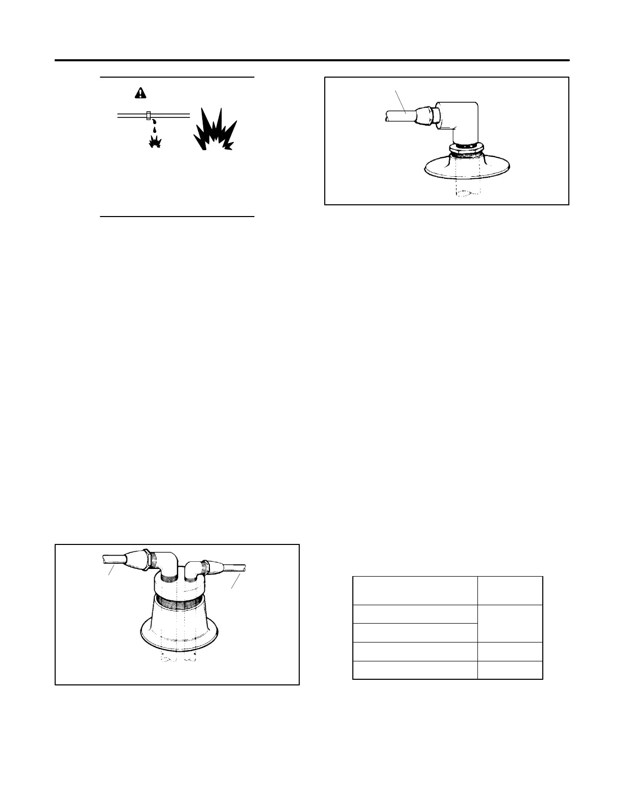
1
1-788
1. Fuel line to generator set
Figure 5-2 Single Dip-Tube Arrangement
Installations with the fuel tank located above the
generator set’s carburetor require an auxiliary fuel
shutoff valve. Close the fuel shutoff valve when not
operating the generator set to prevent fuel leakage.
5.2 Fuel Inlet Line
Use a flexible hose section to connect the metallic line
from the fuel tank to the engine’s fuel pump. USCG
regulations require that metallic lines have a wall
thickness of at least 0.74 mm (0.029 in.). Use seamless
annealed copper, copper/nickel, or copper tubing. The
flexible section allows vibrational motion of the
generator set during operation. Use USCG type-A
hose, marked and tagged according to regulations, for
the flexible section. Support the metallic line within
102 mm (4 in.) of its connection to the flexible section.
See Figure 5-3 for ID sizes of customer-supplied fuel
lines to connect to the fuel pump. Route the fuel lines
from the fuel tank in a gradual incline to the engine. Do
not exceed the height of the generator set and do not run
the fuel lines above the generator set.
See Section 7, Installation Drawings for fuel feed pump
inlet connection.
Model
Fuel Line ID
mm (in.)
5/7.3E and 4/6EF
5/7.3ECD and 4/6EFCD
6 (0.25)
10/13/15EG and 13/15EGZ 8 (0.31)
15/20C and 12.5/16CF 9.5 (0.375)
Figure 5-3 Fuel Line Sizes