TP-5982 4/06 29Section 6 Electrical System
Section 6 Electrical System
Explosion.
Gasoline vapors can cause
explosion and severe injury or
death.
Before starting the generator set,
operate the blower 4 minutes and
check the engine compartment for
gasoline vapors.
WARNING
Ignition-protected equipment. Explosive fuel vapors can
cause severe injury or death. Gasoline vapors can cause an
explosion. USCG Regulation 33CFR183 requires that all
electrical devices (ship-to-shore transfer switch, remote start
panel, etc.) must be ignition protected when used in a gasoline
and gaseous-fueled environment. The electrical devices
listed above are not ignition protected and are not certified to
operate in a gasoline and gaseous-fueled environment such
as an engine room or near fuel tanks. Acceptable locations are
the wheelhouse and other living areas sheltered from rain and
water splash.
Hazardous voltage.
Can cause severe injury or death.
Operate the generator set only when
all guards and electrical enclosures
areinplace.
Moving rotor.
WARNING
Electrical backfeed to the utility. Hazardous backfeed
voltage can cause severe injury or death. Connect t he
generator set to the building/marina electrical system only
through an approved device and after the building/marina
main switch is opened. Backfeed connections can cause
severe injury or death to utility personnel working on power
lines and/or personnel near the work area. Some states and
localities prohibit unauthorized connection to the utility
electrical system. Install a ship-to-shore transfer switch to
prevent interconnection of the generator set power and shore
power.
6.1 AC Voltage Connections
Make AC connections to the generator set inside the
controller box (5/7.3E, 4/6EF, 15/20C, and 12.5/16CF
models) or inside the junction box (5/7.3ECD, 4/6EFCD,
10/13/15EG, and 13/15EGZ models). Typically, the
generator set connects to a ship-to-shore transfer
switch that allows the use of shore/utility power when
docked or generator set power when docked or at sea.
The wiring then connects to a main circuit breaker box
(panel board) that distributes branch circuits throughout
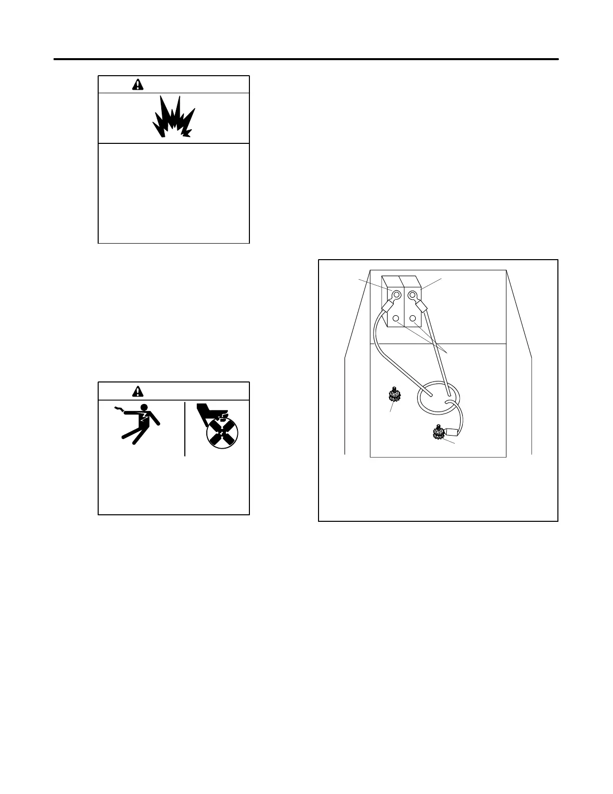
the craft. See Figure 6-1 for AC voltage connections to
the generator set. See Section 8 for reconnection of the
generator set.
12
3
4
5
TP-5811-6
1. Line side connections from generator
2. AC circuit breaker
3. L1/L2 phase (black) leads. Load side customer
connection points.
4. LO neutral (white) lead
5. GRD. ground (green) lead
Figure 6-1 AC Voltage Connections in
Controller Box
6.2 Circuit Protection
The AC circuit breakers protect the generator set from
extreme overload. AC circuit breakers (optional) trip
when they detect a fault in the output circuit.
For circuit breaker application and selection
information, contact an authorized distributor/dealer.
After correcting the fault, reset AC circuit breaker(s) by
placing them in the ON position. Restart the unit. The
unit’s voltage configuration determines circuit breaker
selection.