TP-6079 3/00 11Section 4 Controller Troubleshooting
4.3 Troubleshooting
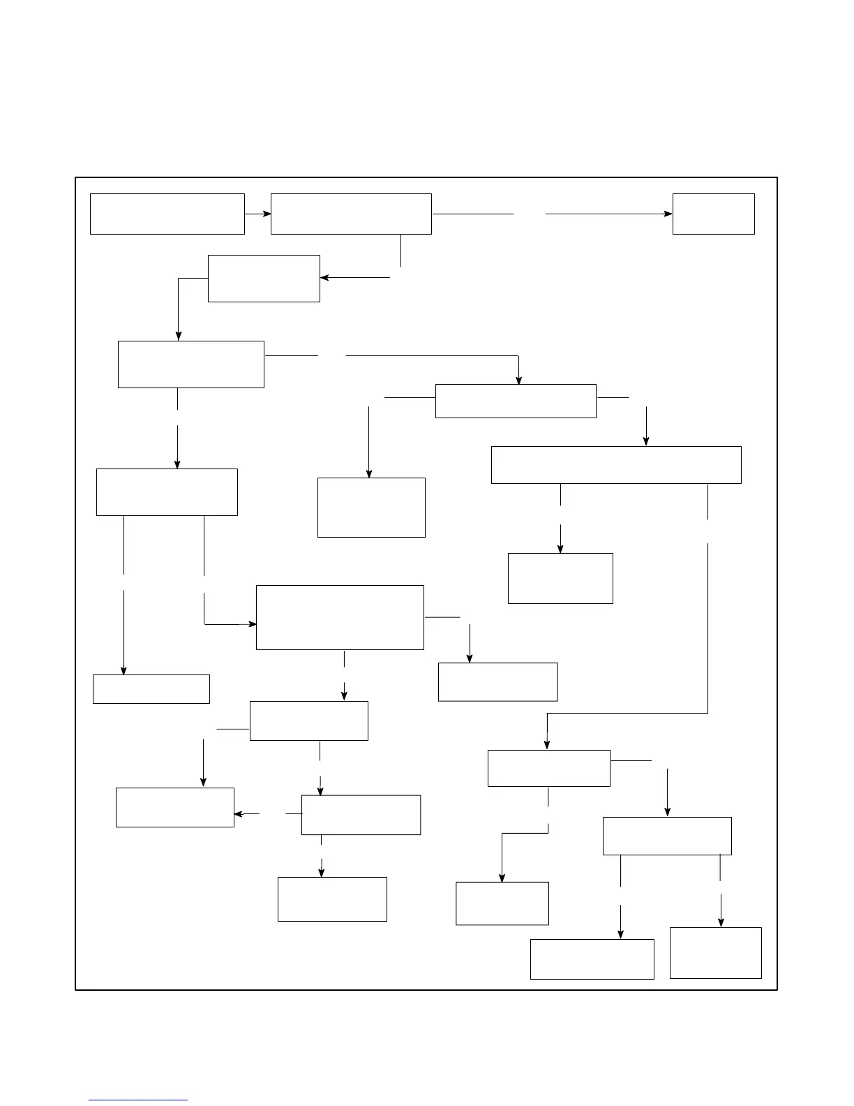
Use the following flow chart as an aid in troubleshooting
the main circuit board and the entire generator set. If the
prescribed remedy does not correct the problem, the
circuit board may have to be replaced. Use this chart for
component testing only. Always check the continuity of
the wires between components. Always disconnect
external components (remote start/stop switches, the
engine gauge panel, dry relay contact kits, etc.) before
performing troubleshooting procedures.
Is the 10-amp controller
fuse functional?
Replace the fuse.
Press the start switch
(local or remote).
Does the engine crank?
Yes
No
Does the K2 relay LED
light while cranking?
Yes
No
Is the K3 relay LED lit?
Yes
No
YesNo
Is there continuity between
N and 47 while pressing
the start/stop switch?
TheK2relayis
faulty. Replace
the circuit board.
Is voltage present
at the starter relay?
Yes
Is voltage present at
the starter?
No
Yes
Replace the starter
relay.
Replace or
repair the
starter motor.
Go to A
(next page).
Replace the
K20 relay.
Is voltage present at the K20 relay coil
(P1-4 connector)?
Yes
No
No
No
Replace the
circuit board.
Check the battery
condition and
connections.
TheK2relayis
faulty. Replace
the circuit board.
Is there 12 volts
at P1--14?
Replace or repair
the wiring harness.
Yes
Yes
No
Is the start/stop
switch functional?
Yes
No
Replace the
start/stop switch.
Figure 4-3 Troubleshooting the Relay Controller Circuit Board (1 of 4)
 Loading...