TP-6079 3/0018 Section 5 Generator Troubleshooting
5.2.2 Voltage Regulator Adjustment
The factory sets the voltage regulator and, under normal
circumstances, the regulator requires no further
adjustment. However, if the voltage regulator has been
replaced or tampered with or if voltage/frequency
reconnection has been done, readjust the voltage
regulator according to the following procedure. See
Figure 5-5. The following paragraphs describe the
voltage regulator components.
33
44
2
1
55
GY R
YOWBK
66
44 33 55
--
+
66
33
3
4
B1
B2
145
6
78
9
1011
12
13
14
15
+
--
2
3
TP-598655
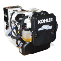
1. Optional remote rheostat
2. Voltage adjustment pot
3. PowerBoostä IIIE voltage regulator
4. Stabilizer pot
5. Volts/Hz pot
6. Stator/rotor connections (for reference only)
7. DC output
8. Rotor
9. 10-amp fuse
10. AC power input (aux.)
11. Main (2 and 1)
12. Control
13. Stator
14. Sensing
15. Main (3 and 4)
Figure 5-5 PowerBoostt IIIE Voltage Regulator
Voltage Adjustment Pot adjusts the generator output
within the range of 100--130 volts.
Stabilizer Pot fine tunes regulator circuitry to minimize
AC voltage fluctuation.
Volts/Hz Pot allows the voltage to drop if the load
imposed on the generator causes the engine speed to
fall below a predetermined frequency (roll-off point).
This reduction of voltage results in a decrease of starting
kW (load) allowing the governor to recover the engine
speed.
Voltage Regulator Adjustment Procedure:
1. Stop the generator set.
2. Turn the remote rheostat, if equipped, to the
midpoint. Turn the voltage and stabilizer pots fully
counterclockwise. Connect the voltmeter to the AC
circuit or an electrical outlet.
3. Start the generator set.
4. Adjust the generator frequency using a frequency
meter. Set the no load speed at 52.5 Hz for 50 Hz
operation or 63 Hz for 60 Hz operation. Rotate the
voltage adjustment pot clockwise to increase the
voltage or counterclockwise to decrease the
voltage to achieve the desired output voltage.
5. Connect a 120-volt light bulb to the AC plug on the
generator set.
6. Rotate the stability pot clockwise until the light bulb
flickers minimally.
7. Readjust the voltage to achieve the desired output
voltage.
8. Disconnect the 120-volt light bulb.
9. Turn the volts/Hz pot completely clockwise to
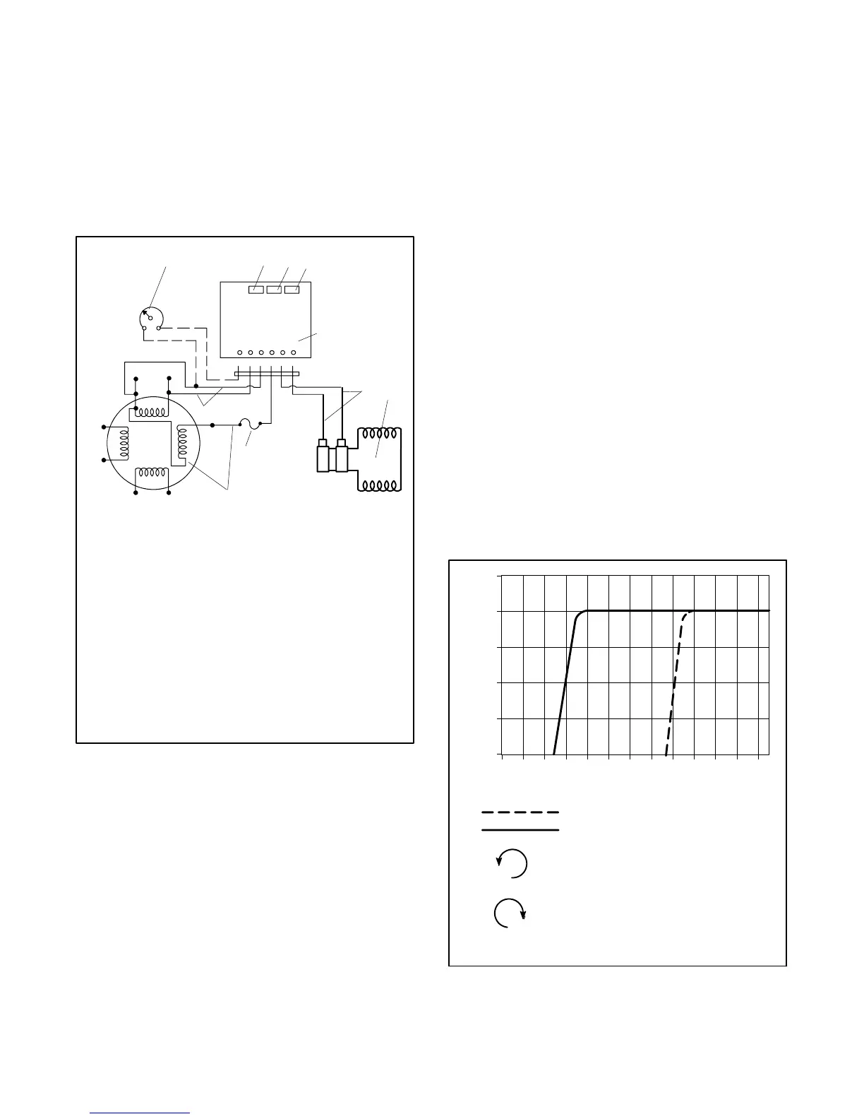
decrease the Hz roll-off point. See Figure 5-6.
100
105
110
115
120
125
40 42 44 46 48 50 52 54 56 58 60 62 64
60 Hz Models
50 Hz Models
Clockwise to decrease Hz roll-off
Counterclockwise to increase Hz roll-off
Frequency (Hz)
Volts (AC)
Figure 5-6 Volts/Hz Roll-Off Chart
 Loading...