Electrical System
116
62 690 05 Rev. HKohlerEngines.com
40/50 Amp High Output Regulated Charging System
F
A
E
H
G
G
G
G
B
C D
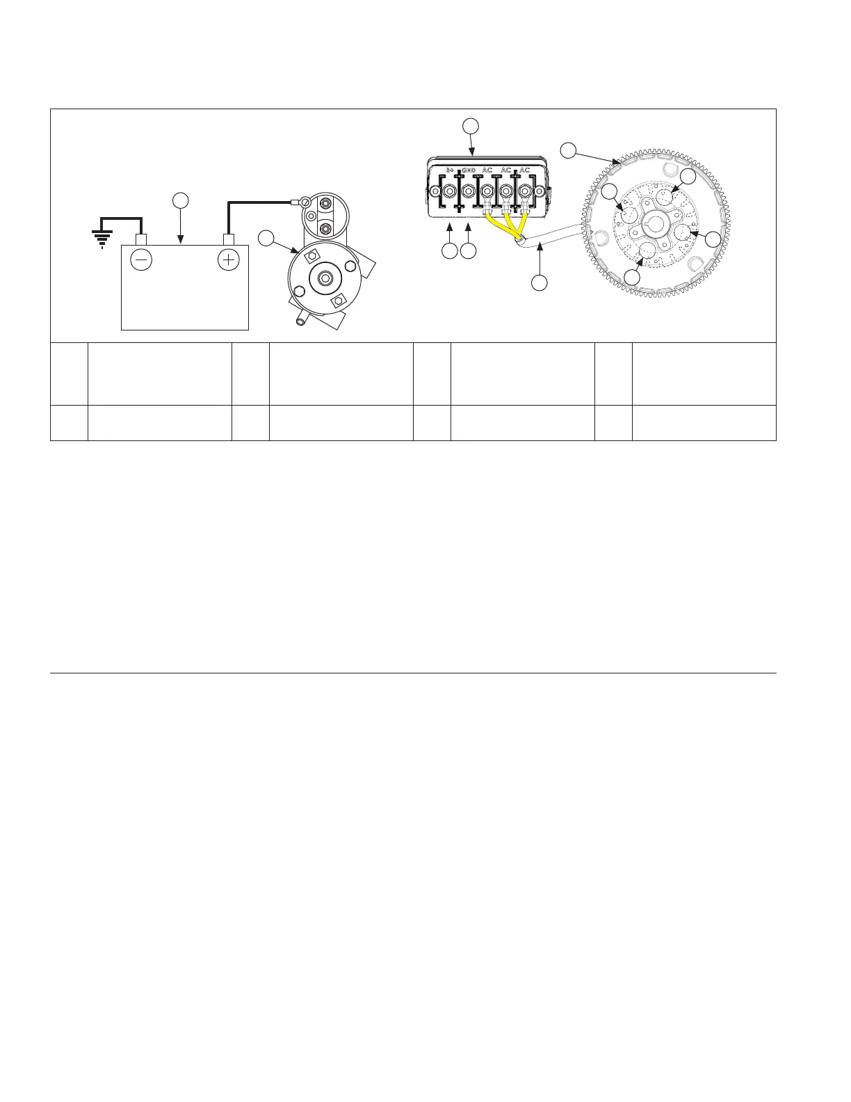
A Battery B Starter C
OEM Supplied B+
Wiring Harness
with Charging
Fuse
D
OEM Supplied
Ground Wiring
Harness
E Rectifi er-Regulator F
Flywheel Stator
Assembly
G
4 Cooling Holes in
Flywheel
H Stator Wires
Stator
Stator is mounted on crankcase behind fl ywheel. Follow procedures in Disassembly/Inspection and Service and
Reassembly if stator replacement is necessary.
Rectifi er-Regulator
NOTE: When installing rectifi er-regulator, take note of terminal markings and install ring terminals accordingly.
Rectifi er-regulator is OEM installed in application. Refer to your equipment manual if rectifi er-regulator replacement is
necessary.
High Output Charging Wiring Harness (OEM Supplied)
In addition to main engine wiring harness (with 3 blade type automotive fuses), engines equipped with a high output
charging system will have a separate charging wiring harness with one (1) large blade type automotive type fuse.
However, 30-amp fuse in main engine wiring harness is then nonfunctional. Purple charge wire ring terminals in main
engine wiring harness are completely sealed and retained using a special heat shrink cap for non use. No service is
required for this circuit. Refer to equipment manual for fuse detail in OEM supplied wiring harness.
Troubleshooting Guide
40/50 Amp High Output Battery Charging System
NOTE: Always zero digital volt-ohm meter (DVOM) on each scale before testing to ensure accurate readings. Voltage
test should be made with engine running at specifi c test condition noted. Battery should be checked for state
of charge (non-operating voltage 12.5 VDC or lower, battery should be charged or replaced).
When problems occur in keeping a battery fully charged or a battery charges at a high rate, battery or charging
system may be at fault. Before performing any testing, battery must be fully charged.
To test charging system:
1. Inspect charging system fuse. If damaged, replace before continuing. Refer to equipment manual for fuse detail in
OEM supplied wiring harness.
2. Visually inspect system components and wiring. Look for damaged or loose wire connections, including battery
cables.
3. Set DVOM to DC volts, place red (positive) lead of tester on rectifi er-regulator negative (-) post and black
(negative) lead to battery negative (-) terminal. Run engine and observe volt reading on meter. If voltage is 0.5
VDC or less, continue with testing. If voltage is higher than 0.5 VDC, inspect and repair wiring/connections as
needed (insuffi cient ground).
4. Perform output tests a and b for charging system using DVOM set to DC volts OR perform test c using carbon pile
test tool.
a. With engine off and key switch in OFF position, measure voltage at battery. If less than 12.4 VDC, recharge
battery and retest. If 12.5 VDC continue with tests.
b. Run engine at high speed no electrical or mechanical load (greater than 3000 RPM). After running 1 minute,
measure voltage at battery.
 Loading...