EFI SYSTEM-ELECTRONIC THROTTLE BODY (ETB)
38
62 690 05 Rev. HKohlerEngines.com
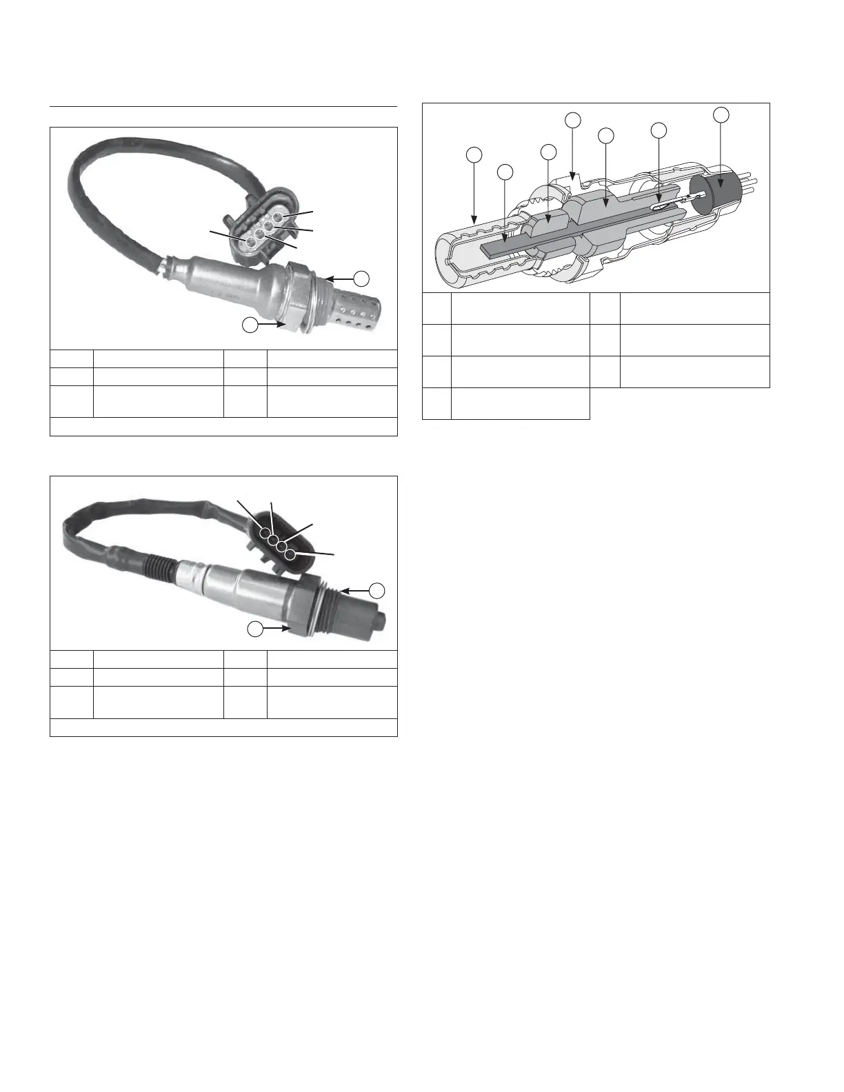
Oxygen Sensor (O2)
Earlier Design Detail
Pin D
Pin C
Pin B
Pin A
A
B
Pin A Heater + Pin B Heater -
Pin C Sensor Output Pin D Sensor Ground
A
22 mm or 7/8 in.
Wrench Size
B
18 mm x 1.5
Thread Size
Installation Torque 50.1 N·m (37 ft. lb.)
Later Design Detail
Pin D
Pin C
Pin B
Pin A
A
B
Pin A Heater + Pin B Heater -
Pin C Sensor Output Pin D Sensor Ground
A
22 mm or 7/8 in.
Wrench Size
B
18 mm x 1.5
Thread Size
Installation Torque 50.1 N·m (37 ft. lb.)
Cutaway Oxygen Sensor Components (O2)
A
B
C
D
E
F
G
A Protection Shield B
Planar Element
and Heater
C Lower Insulator D
Stainless Steel
Housing
E Upper Insulator F
Terminal Connection
to Element
G
High Temp
Water Seal
Temperature must be controlled very accurately and gas
constituents measured to a high degree of accuracy for
absolute sensor measurements. This requires laboratory
equipment to determine a good or bad sensor in fi eld.
Furthermore, as with most devices, intermittent problems
are diffi cult to diagnose. Still, with a good understanding
of system and sensor, it is possible to diagnose many
sensor problems in fi eld.
Using KOHLER
®
Diagnostic System (KDS) Gen 2, see
Tools and Aids, connected to ECU is a useful technique
for observing sensor performance. However, user must
understand that such software reads a signal generated
by ECU. If there is an ECU or wiring problem, readings
could be misinterpreted as a sensor problem. Digital
nature of signal to KDS tool means that it is not reading
continuous output of sensor. A voltmeter can also be
used as an eff ective tool in diagnosing sensors.
Using injector timing test within KDS tool will aid in
testing operation of O2 sensor. See instructions within
help (?) area of injector timing test.