Governor System
9562 690 05 Rev. H KohlerEngines.com
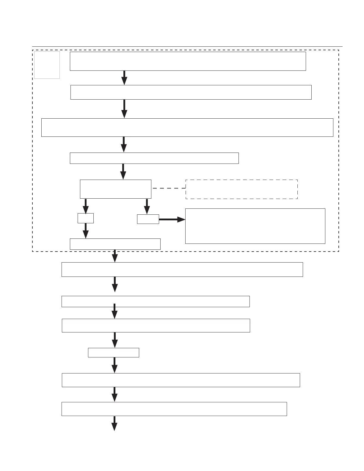
ORIGINAL DESIGN Electronic Governor Troubleshooting Flow Chart Continued
Locate Speed Control input wire. This connection is a single wire red with yellow tracer.
See illustration on page 91.
Unplug and connect a jumper wire to red wire with a yellow tracer on engine wire harness.
Start engine in normal manner as described in Owner’s Manual. (Engine will initially operate at speed it was
last run or shut down, then will go to idle).
Attach open end of jumper wire to positive (+) battery terminal.
Engine speed increases
(if it was at low speed).
Engine speed does not change.
Kohler electronic governor system tests OK. Test
control system of equipment. Refer to Equipment
Manufacturer’s diagnostic procedures for control
system.
12 Volt
Power
Test
Fail
Pass
Operation Input Voltage:
0-1 Volts at Idle/9+ Volts at High Speed.
GCU Circuit Test.
Remove GCU and unplug wiring harness. See illustration on page 88.
Inspect wiring harness for broken wire or bad connections. (Repair/Replace as required).
Test supply ground circuit to GCU using a continuity OHM/tester. Refer to page 90.
Review GCU blink codes with chart on page 92 to identify if a system condition is present.
Continued on next page
Proceed to Ground/Power and OHMs test for GCU. Refer to page 90.
 Loading...