Governor System
96 62 690 05 Rev. HKohlerEngines.com
ORIGINAL DESIGN Electronic Governor Troubleshooting Flow Chart Continued
Test 1: Identify wire ends in connector. Using a digital multi-meter set to lowest scale (0-200 ohms) place
probes onto harness making sure of a good connection. Resistance should be between 47.7 and 58.3 ohms.
Refer to page 90.
If either test fails, DLA is no good and should be replaced. If both tests are good, DLA is neither shorted or open,
and should be good. Another component, connection, or input is most likely at fault.
Test 2: Identify wire ends in connector. Using a digital multi-meter set to lowest scale (0-200 ohms) place
probes onto harness making sure of a good connection. Resistance should be between 47.7 and 58.3 ohms.
Refer to page 90.
Proceed to DLA Circuit Test.
Turn key switch to ON position. Test supply voltage to GCU using volt meter. Refer to page 90 (battery
voltage +/- 1 volt) Note: Prevent Damage to Connector. Do Not Use Oversized Probe Tips.
B+
10
8
12
13
14
1
2
6
7
1B
1A
2A
2B
Application Supplied
Speed Control Input
Operation Input Voltage:
0-1 Volts at Idle/9+ Volts at High Speed
Device
Ground
Power
Speed Signal
ECU Speed Output
(speed signal)
DLA Driver
Controls
DLA
ECU
*
*
Green LED Light
Yellow LED Light
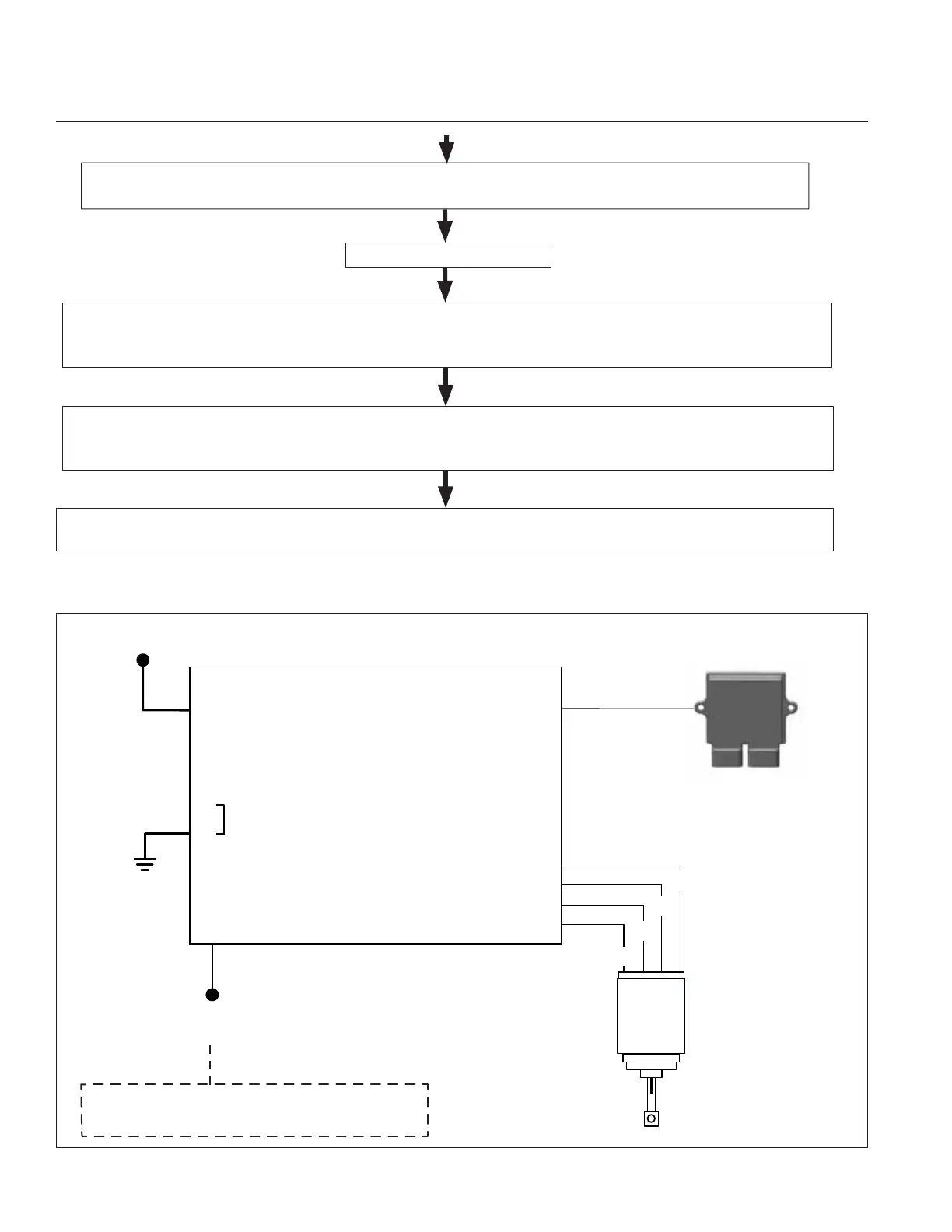
Basic Electrical Diagram of Electronic Governor System
 Loading...