86
Reassembly
KohlerEngines.com 22 690 01 Rev. --
2. Attach speed control bracket to mounting locations
on engine with M6 screws. Position bracket as
marked during disassembly. Torque screws to
11.3 N·m (100 in. lb.) into new holes, or 7.5 N·m
(65 in. lb.) into used holes.
Governor Spring Detail
KS530
RPM Throttle Stop
Governor Spring
Color
3600 Yes Brown
3450 Yes Brown
3400 Yes Yellow
3300 Yes Yellow
3200 Yes Yellow
2800 Yes Yellow
KS540
RPM Throttle Stop
Governor Spring
Color
3600 Yes Yellow
3450 Yes Yellow
3400 Yes Yellow
3300 Yes Brown
3200 Yes Yellow
2800 Yes Blue
KS590
RPM Throttle Stop
Governor Spring
Color
3600 Yes Red
3450 Yes Red
3400 Yes Yellow
3300 Yes Yellow
3200 Yes Yellow
2800 Yes Blue
KS595
RPM Throttle Stop
Governor Spring
Color
3600 No Red
3450 No Red
3400 No Brown
3300 No Brown
3200 No Brown
2800 No Blue
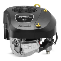
Connect Wire Controls
D
B
A
C
A Choke Linkage B
Control Bracket
Lower Hole
C Control Bracket Slot D
Governor Spring
Location in
Control Bracket
1. If engine has Standard Choke Single Wire Controls,
position choke linkage from carburetor into lower
hole in speed control bracket and out lower slot.
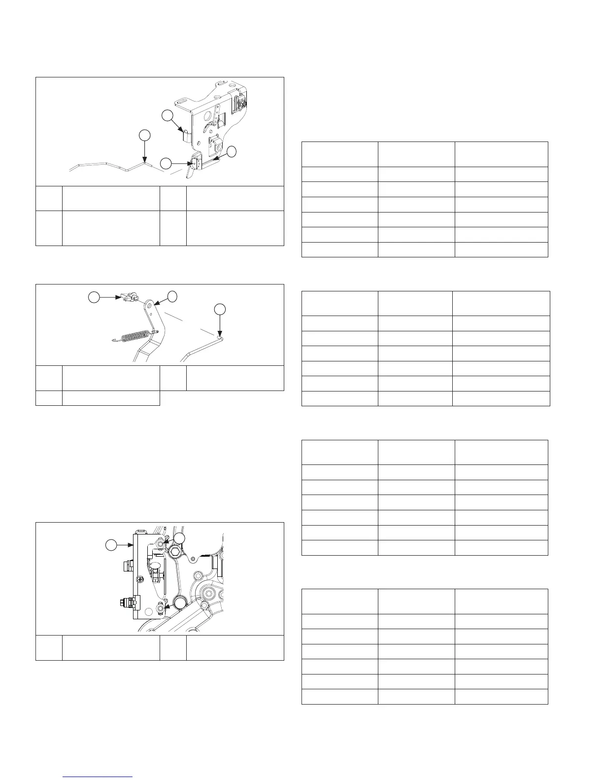
A
C
B
A
Throttle Linkage
Bushing
B Governor Lever
C Throttle Linkage
2. Insert throttle linkage bushing into governor lever;
insert throttle linkage into governor lever and secure
with bushing.
3. Move governor lever toward carburetor, to limit of its
travel (wide-open throttle) and hold in this position.
Do not apply excessive pressure, fl exing or distorting
linkage. Grasp cross shaft with a pliers, and turn
shaft counterclockwise as far as it will go. Torque nut
to 7.7 N·m (68 in. lb.).
Mounting Speed Control Bracket
B
A
B
A
Speed Control
Bracket
B Screw
1. Attach governor spring to throttle lever of speed
control bracket.
 Loading...


