16
KOLDWAVE 2AK (AIRMASTER)
CHECK OUT OF UNIT OPERATION
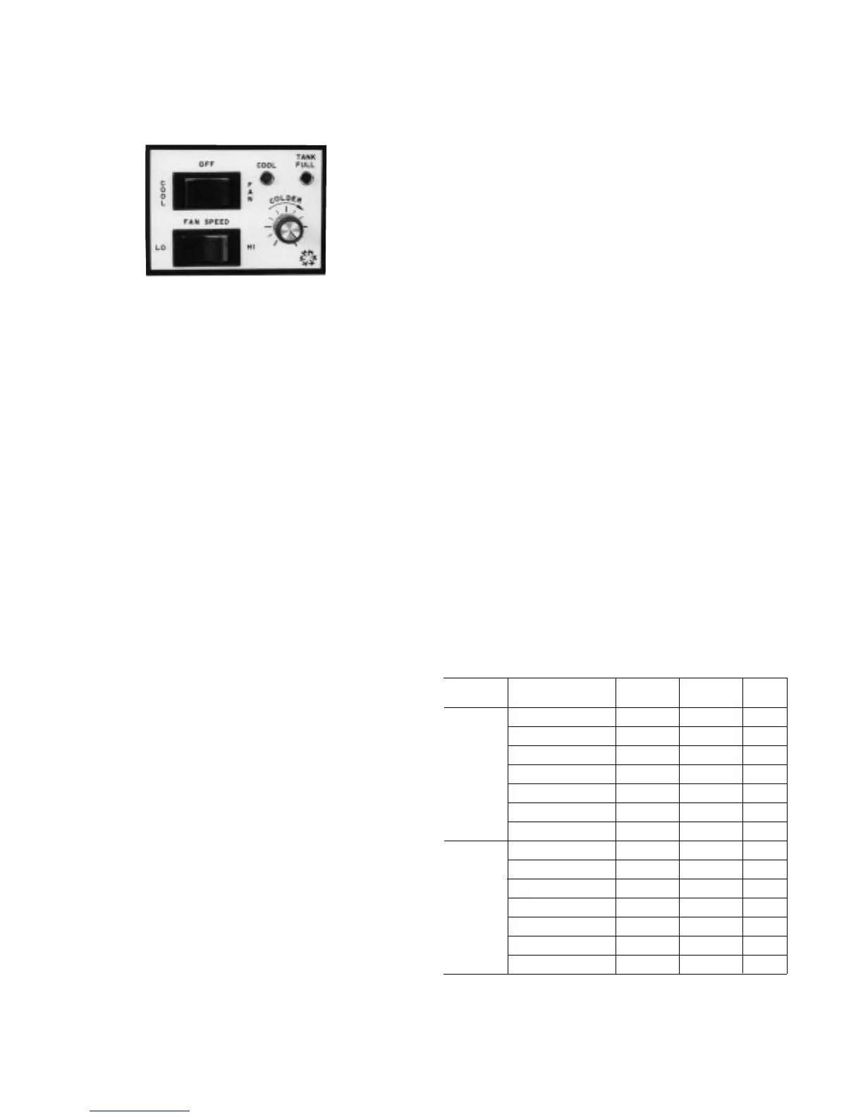
Koldwave Airmaster portable spot cooler provides fan
only air circulation and cooling modes. This is
accomplished by setting the controls to operate in any
of the following:
Fan Only
Plug unit in. Depress the upper mode selector switch
to the right for fan operation. Depress the lower fan
speed selector switch to the left for low fan speed and
to the right for high speed.
TROUBLESHOOTING GUIDE
SERVICE PROCEDURES
Always disconnect power and discharge capacitors
before servicing. Before troubleshooting this system,
read this manual to determine electrical power and
installation requirements to allow the spot cooler to
perform at its maximum efficiency. Refer to general
description, wiring diagrams and photographs to get
an understanding of how the unit functions.
Service other than routine maintenance should be
performed only by a qualified refrigeration service
person. In service/troubleshooting, there is no
substitute for a good understanding of the Koldwave
Airmaster modes of operation, control systems,
components and safety systems (see service
performance chart).
SYSTEM PERFORMANCE CHART
The chart below shows suction and discharge
pressures (PSIG), plus total amp draw with evaporator
fan on high speed, with condenser motor on high
speed and with condenser blower baffle. The
condenser discharge air is ducted into another area
with a 10" diameter, 10' long flexible duct.
Ambient Temperatures Versus
Suction and Discharge Pressures
Discharge
Pressure
317
271
277
216
198
187
171
321
290
282
224
207
193
178
Room
Conditions
104°F DB/80°F WB
95°F DB/83°F WB
95°F DB/75°F WB
80°F DB/67°F WB
75°F DB/62°F WB
72°F DB/60°F WB
67°F DB/57°F WB
104°F DB/80°F WB
95°F DB/83°F WB
95°F DB/75°F WB
80°F DB/67°F WB
75°F DB/62°F WB
72°F DB/60°F WB
67°F DB/57°F WB
Suction
Pressure
104
100
93
78
71
69
65
93
79
93
79
71
68
63
Total
Amps
11.5
10.6
10.5
9.2
8.8
8.6
8.3
13.9
12.9
12.7
11.1
10.6
10.3
9.8
Model
2AK1011
2AK1411M
Use the above chart for reference when suction and discharge
pressure and total amps are a determining factor in analyzing the
problem. Refer to troubleshooting guide when above data can be
useful in determining overcharge or undercharge of unit.
Cooling Cycle
Depress the upper mode selector switch to the left for
cooling. Set the thermostat knob below actual room
dry bulb temperature level. Blue colored light located
next to the upper rocker switch on the panel should
illuminate, indicating the cooling mode of operation.
Allow unit to run fan speed set on high for twenty
minutes. Record temperature of air entering filter and
temperature of air leaving the discharge grille. In a
room of approximately 80°F dry bulb, air temperature
coming from the grille should be approximately 15°F
cooler than air returning to filter. This cycle reduces the
dry bulb temperature and it lowers the wet bulb
temperature by condensing water on the cooling coil
surface. The red colored light located next to the blue
colored light on the panel should illuminate when
condensate tank is full. Refer to “Condensate
Reservoir Tank” section.