II Installation and Commissioning
II.1 Important instructions
n
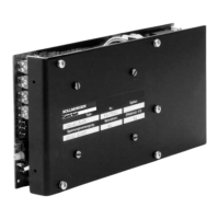
Inspect the nameplate of the controller. Check that the rated voltage and rated current
match the transformer and motor data.
n
Do not switch on the operating voltage before you have read Chapter II of this manual
(Commissioning).
n
Make sure that the maximum permissible rated voltage of 43V~ on terminals 20 , 22 , 32
is not exceeded. An excessive voltage on these terminals will destroy the ballast circuit
in the controller.
n
Make sure that the controller has sufficient ventilation :
up to 8A rated current : vertical mounting, natural convection
above 8A rated current : vertical mounting, additional fan,
forced convection
An incorrect mounting position or a missing fan for rated currents above 8A will lead to
destruction of the controller.
n
Ensure that the cables have an adequate cross-section, to avoid excessive losses and
overheating in the cables.
n
Use twisted cables for setpoint, tacho and motor cables. Tacho and setpoint cables must
also be shielded. Observe the notes in Chapter II.2.1 .
n
Earth the DC-link (Pin 28 or stud —GND/PE). A DC-link circuit which is not earthed can
endanger the operator of the equipment, in the event of an earth short in the motor or fault
currents in the GND lead. Furthermore,the electronics can be destroyed if the earth is
missing when there is a fault. An earth short in the motor will no longer be recognised if
the earth connection is missing.
n
All earth connections must be led out from a common star point, to avoid earth loops and
potential drops in the earth lead. Connect all earth leads to a PE busbar, for instance in
the switchgear cabinet.
n
Do not earth the tachometer cable, since one side of the tacho connection in the
controller has a low-impedance connection to Analog-GND.
n
Take care that the shielding is connected correctly :
Tacho shielding to the controller (Pin 28/stud —GND/PE)
or to the shielding connection terminal
Setpoint shielding to CNC-GND on the controls (single ended)
Motor cable shielding to the PE busbar, using a shielding terminal
n
Loop the BTB contact (Pins 8bd or terminals 8,9) into the safety circuit of the system. Only
so can you be sure that the controller-ready function is monitored.
n
The ±15V auxiliary voltages must not be led out of the cabinet. This avoids capacitively or
inductively induced interference.
Chapter II Installation and Commissioning Page II - 1
Kollmorgen 12.99 Series 04S
Warning
Never connect or disconnect the transistor controller while the system is live.
In unfavourable circumstances this could result in the destruction of the electronics.
Capacitors can still have a residual charge up to 120 sec. after switching off the mains
supply. Measure the voltage in the DC-link, and wait until it has fallen below 20V.
Even when the motor is not rotating, control and power cables can still be live.

 Loading...