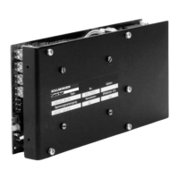
II.2.3 Module back-panels F03SMB and R03SMB
Type: F03SMB for 04S controllers, connections at the back
R03SMB for 04S controllers, connections at the front
The module back-panels are attached from behind in the 19” module. The transistor controller is
inserted into the module and plugged in to the back-panel. The electrical signals are made
available on the back-panel through terminals, studs and flat-pin connectors.
You can find an illustration of the back-panels in Chapter V.3 .
The table below shows the assignments of the signals to the connector pins.
II.2.3.1 Pin assignments for 04S / F03S-MB
Edge conn. 16-pin Short
M7/24 Combicon-conn. Signal name
(pin no.)
(terminal no.) designation (solder print)
2d 1 Setpoint 1+ SW 1 +
2b 10 Pos.Stop PSTOP
2z
2 Setpoint 1- SW1-
4d 3 Setpoint 2+ SW 2 +
4b 11 Neg.Stop NSTOP
4z
4 Setpoint 2- SW2-
6d 6 Tacho– TA
6b 15 Integral Off IAB
6z
5 Tacho+ TA
8d 8 System Ready- BTB
8b 9 contact BTB
8z
16 Enable E
10db 12 Analog-GND (AGND) GND
10z
--- Digital-GND (DGND) ---
12dbz 13 + 15V + 15
14dbz --- – 15V ---
--- 14 --- -15/24
16d
--- 24V-DC aux. voltage ---
16b 7 Armature current R(IDC)
20 M6 stud ~25...43V ~ U1
22
M6 stud ~25...43V ~V1
24 M6 stud + Ucc +Ucc
26 Faston tab - 6.3 + Motor +M
28 M6 stud – Ucc / Analog-GND –GND/PE
30
Faston tab - 6.3 – Motor –M
32 M6 stud ~25...43V ~ W1
Page II - 6 Installation and Commissioning Chapter II
Series 04S 12.99 Kollmorgen
 Loading...