The following notes should make it easier for you to carry out the installation in a sensible
sequence, without overlooking anything.
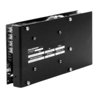
19" rack module in a closed switchgear cabinet.
Follow Chapter I.6.2 .
The site must be free from conductive or aggressive materials.
Check that the transistor controller is properly ventilated and
keep to the permissible ambient temperature, Chapter I.6.2.
Mount the 19" rack module and peripheral components close
together, on an earthed mounting plate in the cabinet (see II.2.1).
Select cables according to EN 60204 and our specification
in Chapter I.6.3.
EMC-conform shielding and earthing: see Chapter II.2.1
Earth the mounting plate, motor housing, isolating transformer,
DC-link, and the CNC-GND of the controls (see Chapter II.2.1).
— Route power leads and control cables separately
— Loop the BTB contact into the safety circuit of the system
— Connect up the logic/digital control inputs to the controller
— Connect up the analog setpoint input and AGND
— Connect the tacho, with all shielding connected to shielding
terminals or EMC connectors
— Connect the motor leads, with the chokes close to the servo
amplifier and shielding to shielding terminals or EMC connectors
— Connect the main power voltage (see Chapter I.6.2 for max.
permissible values, use Seidel isolating transformer 3Txx )
Final check of the implementation of the wiring according to the
wiring diagrams which have been used.
Chapter II Installation and Commissioning Page II - 3
Kollmorgen 12.99 Series 04S
Site
Ventilation
Assembly
Grounding
Shielding
Cable selection
Final check
Wiring
 Loading...