Vers. 270921 Page 24
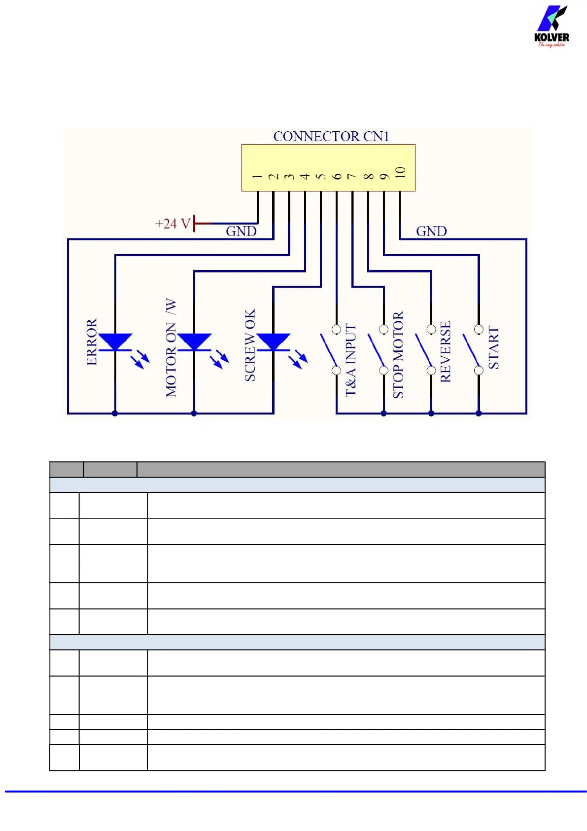
CN1 CONNECTOR – 10 pins
It is situated on the upper part of the back panel.
PIN NAME FUNCTION
OUTPUT
1 +24V
voltage protected. The maximum current consumption is 400mA. CAN NOT BE
2 GND
Common pin. Signals must be taken between this pin
(GND and the respective signal pins
3 ERROR
Error signal: it activates every time an error occurs.
The red led on the front panel will switch on.
4
MOTOR ON
It activates when the motor turns during screwing.
Signal is 24V.
5 SCREW OK
signal. The green led on the front panel will switch on.
INPUT
6 T&A INPUT
External input for making the control unit start to count the
angle. It can be only used in
A/IN and T/IN mode (see T&A paragraph)
7
STOP
MOTOR
Remote motor stop. If it’s activated the message “STOP MOTOR ON” appears on the
display. The motor will stop and won’t start working again as long as the contact is
closed
8 REVERSE
Remote motor start with torque control while unscrewing.
9 START
Remote start with torque control while screwing.
10 GND
The desired function is activated through a contact between this pin and