64
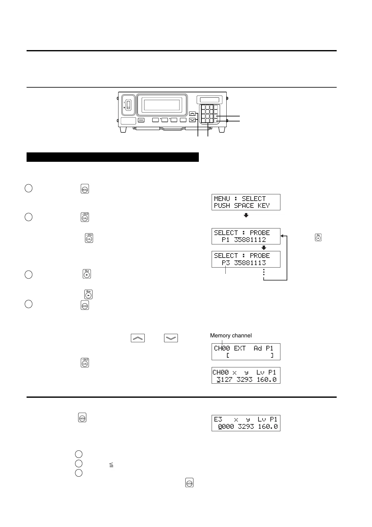
2. Setting/changing the target color by entering values
This method can be used for memory channel CH00 only.
[Operating Procedure]
1
4
2
3
When the optional 4-Probe Expansion Board CA-B04 is used
Select the probe no. to which you want to set the target color. The target color can be set independently for each
probe connector ([P1] to [P5]) for each memory channel.
1 Press the key.
The LCD display section will switch to the menu selec-
tion screen.
2 Press the key to open the PROBE selec-
tion screen.
Each time the key is pressed, the screen will switch
in the order PROBE → SYNC → ID Name input →
RANGE → Measurement Speed → Number of Digits →
RS232C Baud Rate → PROBE.
3 Press the key to display the probe no.
you want to select.
Each time the key is pressed, the probe no. switches in the order [P1]
…
.
4Press the key to confirm the selection.
* By default (factory setting), the instrument is set so that [P1] will be selected automatically when the POWER switch is set to ON. If you
want to change this setting, refer to page 30.
1. Press the MEMORY CH and keys
until the memory channel CH00 appears.
2. Press the key.
In the LCD display section, the current target color val-
ues are displayed.
<Error Messages in LCD Display Section>
…
For other error messages, refer to page 107.
● “E3” (after the key is pressed)
• Cause : An attempt was made to set Incorrect target
color values.
Incorrect calibration values mean the following.
1 One of x, y and Lv is “0”.
2 1–x–y 0
3 Va lues which are beyond the instrument’s calculation capability or contradicting values.
• Action : Enter correct values and then press the
key.
Menu selection screen
PROBE selection screen
Probe no.
Press the key
until the desired
probe no. appears.
MENU : SELECT
PUSH SPACE KEY
SELECT : PROBE
P1 35881112
SELECT : PROBE
P3 35881113
E3 xyLvP1
0000 3293 160.0
_
Memory channel
CH00 EXT Ad P1
[]
CH00 x y Lv P1
3127 3293 160.0
_