Do you have a question about the Konica Minolta JS-506 and is the answer not in the manual?
Provides important notes and conditional steps for installing the job separator on main machine models.
Turn off power, unplug, and remove protective materials and accessory parts before installation.
Steps for removing the output tray and covers from the main unit during installation.
Installing the film and sensor unit, including removing knockouts and securing components.
Connecting the sensor unit connector and routing the harness through wire saddles and edge covers.
Securing the upper tray and attaching the job separator to the main unit using provided screws.
Plugging in job separator connectors, securing cable ties, and reattaching covers.
Power off, unplug, remove protective materials, and take out accessory parts for 367/287/227 models.
Removing the output tray and guide from the main unit for installation on specific models.
Steps for removing covers and extracting knockouts from the main unit's chassis.
Attaching the film and sensor unit, connecting the sensor unit, and routing the harness.
Installing the upper tray and securing it with screws to the main unit.
Mounting the hook and attaching the job separator to the machine as per instructions.
Securing the job separator with screws and plugging in connectors to the main unit.
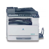
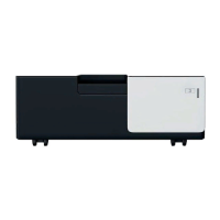
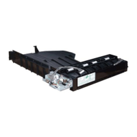
The JS-506 is a Job Separator designed for use with a range of Konica Minolta multifunction printers (MFPs). Its primary function is to separate print jobs, enhancing document management and organization, particularly in busy office environments.
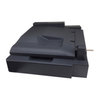
The Job Separator is an optional accessory that integrates with compatible Konica Minolta MFPs to provide physical separation of printed output. This is achieved through an upper tray and a mechanism that guides different print jobs to distinct output locations, preventing intermingling of documents from various users or tasks. The installation process involves attaching a sensor unit, an upper tray, and the main job separator unit to the MFP. The sensor unit plays a crucial role in detecting and managing the paper path, ensuring proper job separation. The device is designed to be installed on the main unit of the MFP, often requiring the removal and reattachment of existing covers and internal components to integrate seamlessly.
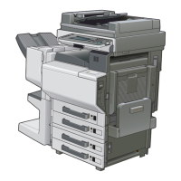
The JS-506 Job Separator is compatible with a wide array of Konica Minolta MFP models, including:
The product codes associated with these compatible machines include: A5AY, A5C0, A5C1, A5C2, A5C4, A2XK, A4FJ, A161, A4FK, A4FM, A7PU, A7PY, A61D, A61E, A61F, A61G, A61H, A789, A7AH, A7AK.
The installation requires specific screws:
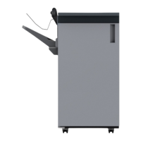
The Job Separator is designed to be user-friendly once installed. Its primary usage feature is the automatic separation of print jobs, which helps users easily identify and retrieve their documents without sorting through mixed output. The upper tray serves as a dedicated output bin for separated jobs.
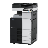
For models C554e/C454e/C554/C454/554e/454e, the installation of the JS-506 is conditional on whether the optional Output Tray OT-506 is installed. If the output tray has a "snap-fit hook," the installation procedure differs slightly, guiding the user to specific steps. If it lacks the snap-fit hook, a different set of steps is followed. This adaptability ensures compatibility with various configurations of the host MFP.
The installation process involves several key steps that highlight its usage features:
The manual primarily focuses on installation, but some aspects hint at maintenance considerations:
Overall, the JS-506 Job Separator is a well-integrated accessory designed to streamline document output for a wide range of Konica Minolta MFPs, with a detailed installation process that emphasizes precision and careful handling of components to ensure optimal performance and longevity.
| Brand | Konica Minolta |
|---|---|
| Model | JS-506 |
| Category | Printer Accessories |
| Language | English |