500 SERIES INSTALLATION MANUALJULY 2016 PAGE 15
Provided the stern drive and gimbal carrier (if applicable) are
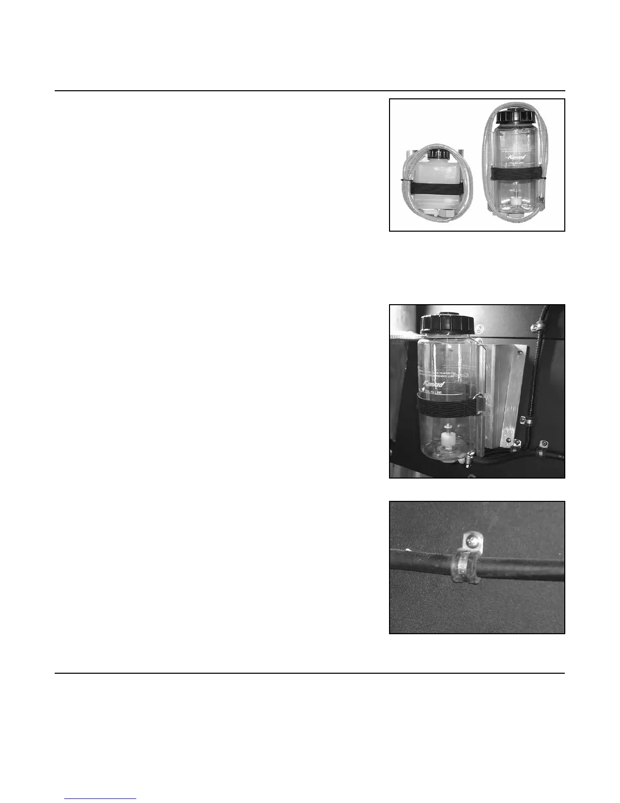
purged, the oil level can be checked at the remote oil reservoir. The
bottle should be visible upon opening the engine compartment
cover. There are two (2) different styles of reservoirs, one (1)
reservoir is used per drive. The one (1) pt. (.47 l) reservoir
assembly (with a rectangular bottle) has a part number of 30-
179. The part number of the bottle only is 10-431. The one (1)
qt. (.95 l) reservoir assembly (with a cylindrical bottle) has a
part number of 30-295. The part number of the bottle only is 30-
941 (See Figure 3A). Manufacturer will have predetermined the
correct reservoir.
3.1 This is a gravity feed system. Position the oil reservoir
bottle and bracket on the transom, keeping it as high as
possible. The oil bottle must be above the line input to
the stern drive and gimbal carrier (if applicable). When
considering the position make sure that there is enough
clearance to ll the bottle with oil. Keep in mind that
the bottle may be removed from the bracket to be lled,
however, it must be secured again after lling is complete
(see Figure 3B).
NOTE: Pay attention to the placement of the bottle
bracket to ensure that they will clear the steering cylinder
ram or other moving parts that will potentially be mounted
in later steps.
NOTE: The connecting oil hoses must be fastened to the
transom within 6 in. (15 cm) of the oil bottle and every 6
in. (15 cm) afterward (see Figure 3C). Oil hoses must not
be kinked or looped such that it impedes gravity feed.
3.2 For berglass hulls, mount the bottle bracket with two
(2) lag screws. For aluminum hulls, attach bottle bracket
to hull by welding or using a mounting plate (see Figure
3B).
Step 3: Oil Reservoir Installation
FIGURE 3A
FIGURE 3B
FIGURE 3C
 Loading...

