500 SERIES INSTALLATION MANUALJULY 2016 PAGE 29
Step 6: Alignment Procedures
NOTE: General vessel installation plans should be di-
rected at near straight shaft angles. The shaft’s maximum
misalignment tolerances should be reserved for temporary
movement of components while the vessel is underway.
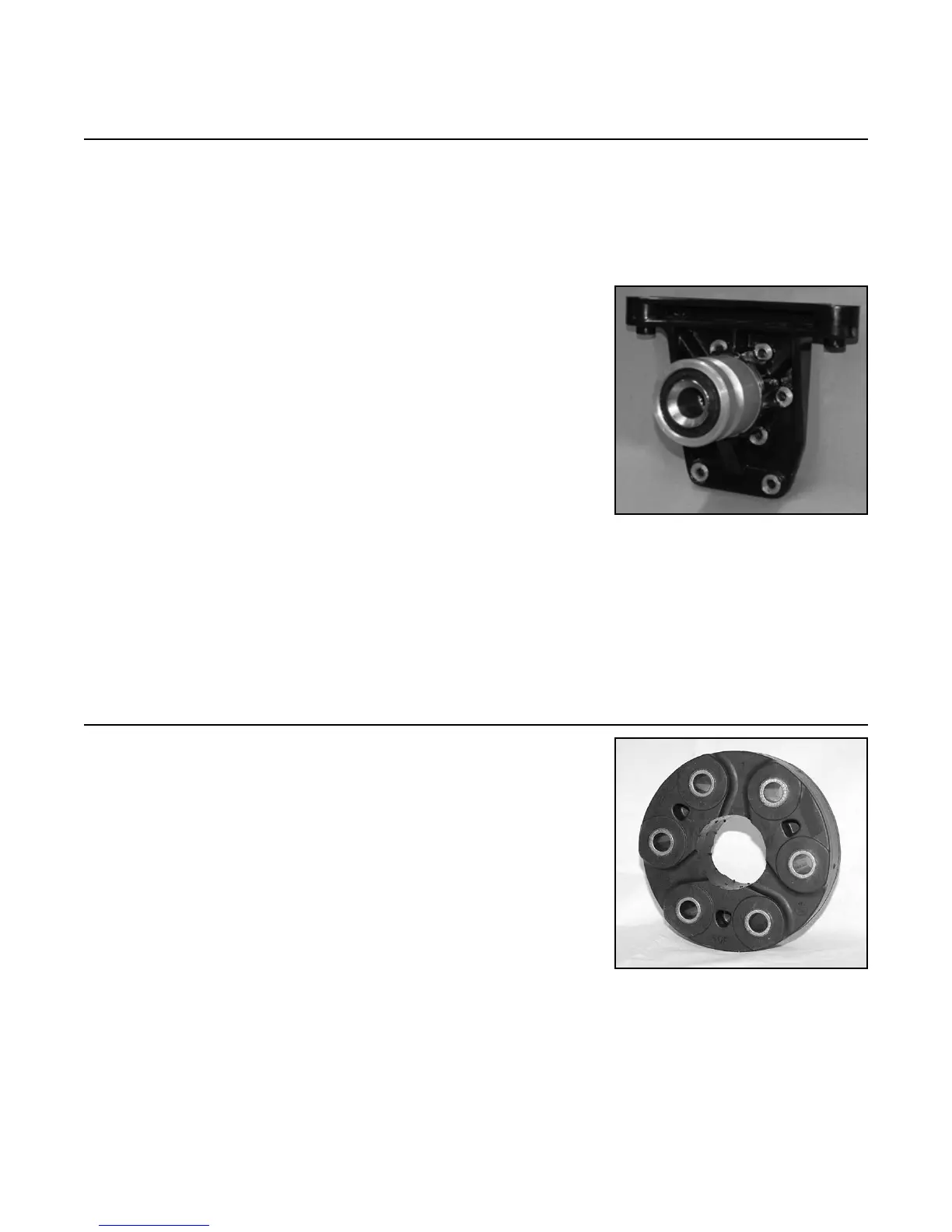
A) Direct Couple Rear Mount
with Tailpiece
1) Attach transmission to engine.
2) Attach tailpiece unit to transmission.
3) Slide o-ring on to tailpiece.
4) Lightly grease o-ring.
5) Position engine into vessel.
6) Slide tailpiece into gimbal housing bore.
7) Fasten tail piece assembly to tail piece
mounting plate.
8) Use Tool TO-094 for alignment. Shaft must
slide easily into tailpiece spline until fully
engaged to the limiting shoulder surface.
NOTE: See Step 19 for complete detailed instructions.
B) Direct Rubber Coupling
1) Rubber coupling must be oriented for transmis-
sion output rotation in forward mode
as stated
in Steps 15 on pages 64 - 67 in this manual.
2) Install engine transmission and shaft to gimbal
carrier trilobe ange. Do not tighten any bolts.
3) Transmission output ange must be indicated
to the gimbal carrier outside diameter (and
face) within .003 in. (.076 mm). Adjust engine
mounts accordingly.
4) Tighten all fasteners to specied torque of
70 lb. ft. (95 Nm).
FIGURE 6A
FIGURE 6B