10
(→p.35, 97)
By holding down the [IN/LOC1] key and pressing
the [OUT/LOC2] key, you can listen to the audio
between the IN–OUT points.
27 [AUTO PUNCH] key
This key is used to turn the Auto Punch-in/out
function on/off, to set the pre/post roll time, and
to verify the start/end locations. (→p.28, 98)
This key will light when the Auto Punch-in/out
function is on.
28 [LOOP] key
This key is used to turn the Loop function on/off
for playback or recording, and to verify the start/
end locations. (→p.99)
This key will light when the Loop function is on.
29 [UNDO] key
After recording or editing a track, you can use the
Undo function to return the data to its prior state,
and then (if desired) use the Redo function to can-
cel the Undo and go back to the edited data.
Up to 99 prior recording or editing operations can
be undone. You can select from 1, 8, or 99 levels of
undo. (→p.99)
This key will light when Undo or Redo is available.
30 [TRIGGER] key
This is the on/off key for the Trigger Recording
function, which causes recording to begin automat-
ically in response to an audio input. This key is also
used to set the threshold level and pre-trigger time.
(→p.31, 100)
This key will light when the Trigger Recording
function is on.
31 [SCRUB] key
This key turns the Scrub, Play To/From, and Slow
Play functions on/off. The key will light when the
Scrub function is “On.” These functions are used
by controlling the [VALUE] dial or TRANSPORT
keys. (→p.101)
32 [ENTER] key
This key is used to finalize a parameter selection, or
to turn a parameter on/off.
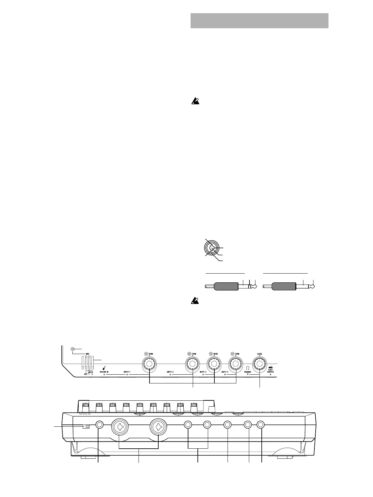
1 MIC (built-in mic)
2 [MIC] on indicator
3 [MIC] switch: OFF, INPUT 1, INPUT 2
OFF: The built-in mic is turned off. (LED dark)
INPUT 1: The built-in mic is input from [INPUT 1].
(LED lit)
INPUT 2: The built-in mic is input from [INPUT 2].
(LED lit)
When the [MIC] switch is set of the INPUT 1 or
INPUT 2, that input will used as the mic input, and
the source connected to that jack will not be input.
The input priority order is as follows.
• 1 [MIC], 2 [GUITAR IN], 3 [INPUT]
If you are not using the internal mic, turn the [MIC]
switch off so that unwanted sound is not input
from the mic.
4 [GUITAR IN] jack
A guitar or bass guitar can be input here.
This is an unbalanced 1/4" (6.3 mm) input jack
with 1 M-ohm impedance.
5 [INPUT 1], [INPUT 2] jacks
Audio sources such as mic or line (keyboard etc.)
can be connected here.
These are combo-type balanced inputs that com-
bine XLR jacks and 1/4" TRS phone jacks.
Unbalanced phone plugs can also be connected.
If you connect a plug to the [GUITAR IN] jack, no
signal will be input from the [INPUT 1] jack. If you
wish to use the [INPUT 1] jack, disconnect the plug
from the [GUITAR IN] jack.
1
2
9
7
3
46810115
Front panel
1/4" TRS phone jack
XLR jack
1: GND
2: HOT
3: COLD
3
1
2
Balanced phone plug Unbalanced phone plug
GND COLD HOT
GND HOT