Do you have a question about the KOSTAD CPC 50 and is the answer not in the manual?
The Kostad Modular Fast Charging Station, models CPC 50/60|90|120, is a multi-standard charging station designed for electric vehicles. It supports various AC and DC charging standards, ensuring compatibility with a wide range of EVs.
The charging station provides DC charging via CCS2 Combo plug type 2, offering up to 120 kW charging power at a maximum of 920 V or 200 A. It also supports CHAdeMO V0.9.x to 1.2, with up to 50 kW charging power at a maximum of 125 A. For AC charging, it offers Type 2 connections with 22 kVA or 43 kVA (single to 3-phase). The 22 kVA AC version can be ordered as a socket or a cable/plug combination, while the 43 kVA version is only available with a fixed cable and plug. An optional phase symmetry monitor can be selected for the 43 kVA version, in accordance with VDE-AR-N 4100.
To initiate a charging process, vehicle owners must authenticate themselves, typically via RFID, mobile app, or credit card at the payment terminal. "Free charging" is also possible if enabled by the operator. The station can charge one connected EV on the DC side as standard, with parallel DC charging of two EVs available as an option. Parallel charging of two e-vehicles is also possible using both AC and DC outputs simultaneously.
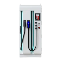
The device features a control panel/HMI (Human Machine Interface) for user interaction, an RFID reader, and an EMERGENCY STOP button. LED lighting is present at each cable outlet to indicate the charging point's status. The charging station is accessible from all sides, with side doors and a rear wall secured by TX30-TR-(Pin) screws. The control system, including 24 V power supply, router, communication box, and data network connection, is installed separately from the power electronics.
The charging station's article number, found on the type plate, indicates specific configurations such as AC metering for DC and AC sides (with or without ERK), and AC voltage (e.g., 400 V). The device supports various RFID card systems, including NFC forum tags (type 1-4), ISO 14443 A/B (Mifare, DESFire), ISO 18092 ECMA-340 (NFC Peer-to-Peer, Sony FeliCa), ISO 15693 (ICODE SLI, LEGIC Advant), and LEGIC Prime, as well as 125 kHz and 134.2 kHz systems (AWID, Cardax, CASI-RUSCO, EM4100, etc.). The maximum permissible voltage drop is country-specific, requiring compliance with local regulations. The device is suitable for industrial applications; in domestic environments, it may cause radio interference, requiring appropriate measures from the operator.
The HMI distinguishes between a user area and a service area. The user area displays charging point status, allowing users to select charging points, authenticate, and start/stop charging. The display language can be changed via a flag symbol. The status of charging points is indicated by separate buttons, showing the type (CCS, CHAdeMO, or Type 2 AC) and current status. LED light strips indicate the status: green for ready, blue for charging, magenta for reserved, red for malfunction, and off for unavailable. The service area, accessible via a password-protected login, allows authorized personnel to configure various settings. These include station configuration (charging point numbers, name, authentication methods), RGB LED settings (color definitions for different operating states), temperature thresholds for power adjustment, operator settings (user management, maximum feed-in power, screensaver modes, night mode, LED life sign intervals, RFID card sound feedback), OCPP parameters for backend communication, payment terminal settings, and operating schedules. The "Simulation" menu allows for simulating charging processes for diagnostic purposes, without a connected vehicle or with a defined test system. This feature is intended for trained personnel and requires the charging point to be in an operational state with no pending faults. High voltages (up to 920 V) can occur at the connector during simulation, so safety precautions must be observed.
Annual maintenance and servicing work include checking the emergency stop circuit (door switch, emergency stop button), auxiliary relay earth fault, heating, ventilation, and LEDs. For cooled cables, the recooling unit, cables, and cable glands must be checked for tightness and leaks. The plug holder, plug, and cable insulation should be inspected, and measured values checked. A test charge, loop measurement, and residual current circuit breaker test should be performed. The control panel needs calibration, and plant logbook/measurement logs must be documented. Filter mats should be checked regularly, at least once a year, and replaced if soiled to ensure sufficient air supply. Fans must be replaced after 30,000 hours of active charging. Charging cables and plugs should be inspected for tampering, damage, and foreign objects, and replaced after approximately 10,000 mating cycles. The replacement of AC sockets and charging cables for CPC 60|90|120 models should only be carried out by certified and trained specialist personnel. The device includes counters for charging processes and fan operating hours to aid in maintenance planning. These values are retained during software updates and stored in the control unit. The control cabinet door contact switches off dangerous voltage on directly touchable parts, with other areas protected by finger safety or requiring tools for access. Screw terminals of the mains connection box should be checked regularly for tightness and defects. For disposal, the charging station components, primarily steel, copper, and aluminum, should be separated for recycling according to local regulations. Auxiliary materials and chemicals must also be disposed of environmentally. Packaging materials, including wooden pallets and aluminum composite film, should be recycled or disposed of via waste incineration.
| Brand | KOSTAD |
|---|---|
| Model | CPC 50 |
| Category | Battery Charger |
| Language | English |