21
2
01 / 2020 © 2020 KOSTAL Solar Electric GmbH
Device and system description
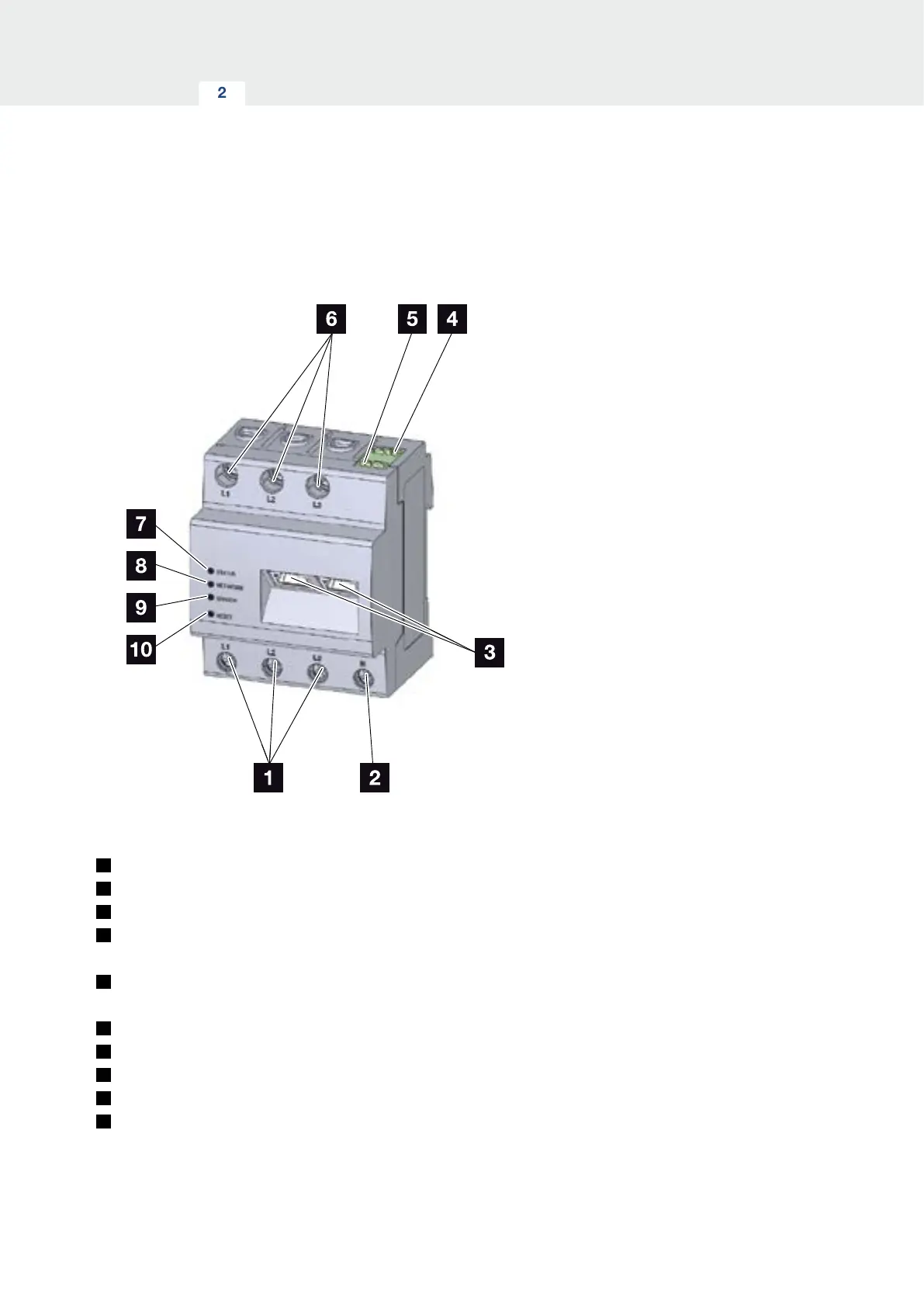
2.2 The KOSTAL Smart Energy Meter
Fig. 7: Energy meter
1
Inputs for external wires L1, L2, L3
2
Neutral wire N
3
2 x LAN connection
4
RS485 connection (A)
Pre-configured for PIKO IQ/PLENTICORE
5
RS485 connection (B)
Pre-configured for PIKO MP plus
6
Outputs for external wires L1, L2, L3
7
Status LED
8
Network LED
9
Sensor LED for RS485 bus
10
Reset button