KRAMER: SIMPLE CREATIVE TECHNOLOGY
Your TP-125EDID XGA / Audio / Data Line Transmitter
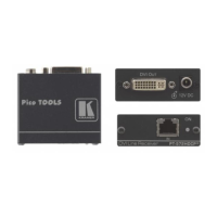
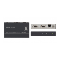
Table 6: TP-125EDID XGA / Audio / Data Line Transmitter Features
1 12V DC +12V DC connector for powering the unit
2 AUDIO IN 3.5mm Mini Jack Connects to the audio source
3 RS-232 Terminal Block Connector Connects to the PC or the Remote Controller (see section 5.2)
4 LINE OUT RJ-45 Connector
Connects to the LINE IN RJ-45 connector on the TP-126
UXGA / Audio Line Receiver
5 UXGA IN 15-pin HD (F) Connector Connect to the UXGA source
6 EDID
1
CAPTURE Button Press to acquire the EDID information from the display
7 STATUS LED Illuminates during normal operation; blinks when acquiring the
EDID
8 ON LED Illuminates when receiving power
6.1 Connecting the TP-125EDID XGA / Audio / Data Line Transmitter
You can use the TP-125EDID UXGA / Audio / Data Line Transmitter together
with the TP-126 UXGA / Audio / Data Line Receiver
2
Before connecting the transmitter and receiver system you can acquire the
EDID from the display or set the system to the default EDID, see section
to configure a twisted pair
transmitter and receiver system, to transmit the video, audio and RS-232 control
signals via CAT 5 cable.
9
To connect the TP-125EDID and the TP-126 to create a twisted pair transmitter
and receiver system, as the example in
Figure 7 illustrates, do the following:
1. On the TP-125EDID, connect:
An UXGA source (for example, the graphics card on a laptop) to the
UXGA IN 15-pin HD (F) connector and an audio source to the Audio
IN 3.5mm mini jack, for example, using a Kramer C-GMA/GMA
cable (VGA 15-pin HD (M) +Audio jack to VGA 15-pin HD (M)
+Audio jack)
3
An RS-232 cable with a 9-pin D-sub connector at one end to the
laptop, and a 3-pin terminal block connector at the other end to the
TP-125EDID RS-232 port
4
2. On the TP-126, connect:
The UXGA OUT 15-pin HD (F) connector to the AV display system
1 See section 9
2 Download up-to-date Kramer user manuals from our Web site at http://www.kramerelectronics.com
3 Not supplied. The full list of Kramer cables is on our Web site at http://www.kramerelectronics.com. Alternatively, you can
connect an UXGA source to the UXGA IN 15-pin HD (F) connector, and a separate audio source to the AUDIO IN 3.5mm
mini jack
4 As defined in
Figure 5 and Table 4