KRAMER: SIMPLE CREATIVE TECHNOLOGY
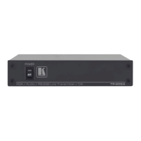
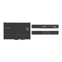
Your PT-110EDID XGA / Line Transmitter
Table 9: PT-110EDID XGA Line Transmitter Features
1 XGA IN 15-pin HD (F) Connector Connect to the UXGA source
2 12V DC +12V DC connector for powering the unit
3 EDID
CAPTURE Button Press to acquire the EDID information from the display
4 STATUS LED Illuminates during normal operation; blinks when acquiring the
EDID
5 LINE OUT RJ-45 Connector
Connects to the LINE IN RJ-45 connector on the TP-120
UXGA / Audio Line Receiver
6 VS Switch Slide up to set the V SYNC to NEGATIVE polarity;
slide down
2
to set the V SYNC to NORMAL polarity
7 HS Switch Slide up to set the H SYNC to NEGATIVE polarity (NEG);
slide down
2
8
to set the H SYNC to NORMAL polarity
ON LED Illuminates when receiving power
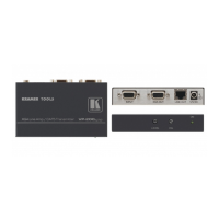
7.1 Connecting the PT-110EDID XGA / Line Transmitter
You can use the PT-110EDID XGA Line Transmitter together with the TP-120
XGA Line Receiver
3
Before connecting the transmitter and receiver system you can acquire the
EDID from the display or set the system to the default EDID, see section
to configure an XGA-to-Twisted Pair Transmitter and
Receiver system.
9
To connect the PT-110EDID XGA Line Transmitter with the TP-120 XGA
Line Receiver, as the example in
Figure 10 illustrates, do the following:
1. On the PT-110EDID, connect the XGA source (for example, the 15-pin
HD output from a computer’s graphics card) to the XGA INPUT 15-pin
HD (F) connector.
2. On the TP-120, connect the XGA OUT 15-pin HD (F) connector to the
XGA acceptor (for example, a monitor).
3. Connect the LINE OUTPUT RJ-45 connector on the PT-110EDID to the
LINE IN RJ-45 connector on the TP-120, via CAT 5 cabling (with a range
of more than 300ft (>100m)).
4. On both
4
1 See section
the PT-110EDID and the TP-120, connect the 12V DC power
adapter to the power socket and connect the adapter to the mains electricity.
The signal from the XGA source is transmitted via CAT 5 cable, decoded
and converted at the XGA OUT 15-pin HD (F) connector to the XGA
acceptor.
9
2 By default, both switches are set down (for normal V SYNC and H SYNC polarity)
3 Download up-to-date Kramer user manuals from our Web site at http://www.kramerelectronics.com
4 For distances of up to 100 meters you can connect a power adapter to either the PT-110 or TP-120. Above it, both sides
should be fed with power