DM4E, DM4, DM4 DL Operating Manual
Page 9
Model DM4E
Model DM4 DL
2.4 Getting Started
NOTE:
DM4E, DM4 and DM4 DL feature automatic probe
zero for standard probes and automatic probe recognition for
DIALOG Intelligent Transducers.
Model DM4
Read “Important Notices” at the beginning of this manual, and
Chapter 6, “Application Notes,” for important information on test
conditions that affect measurement results.
Select a suitable probe (Section 5.2) and connect it to the probe
connector on the top panel. See Section 4.3 to select a report
language other than English.
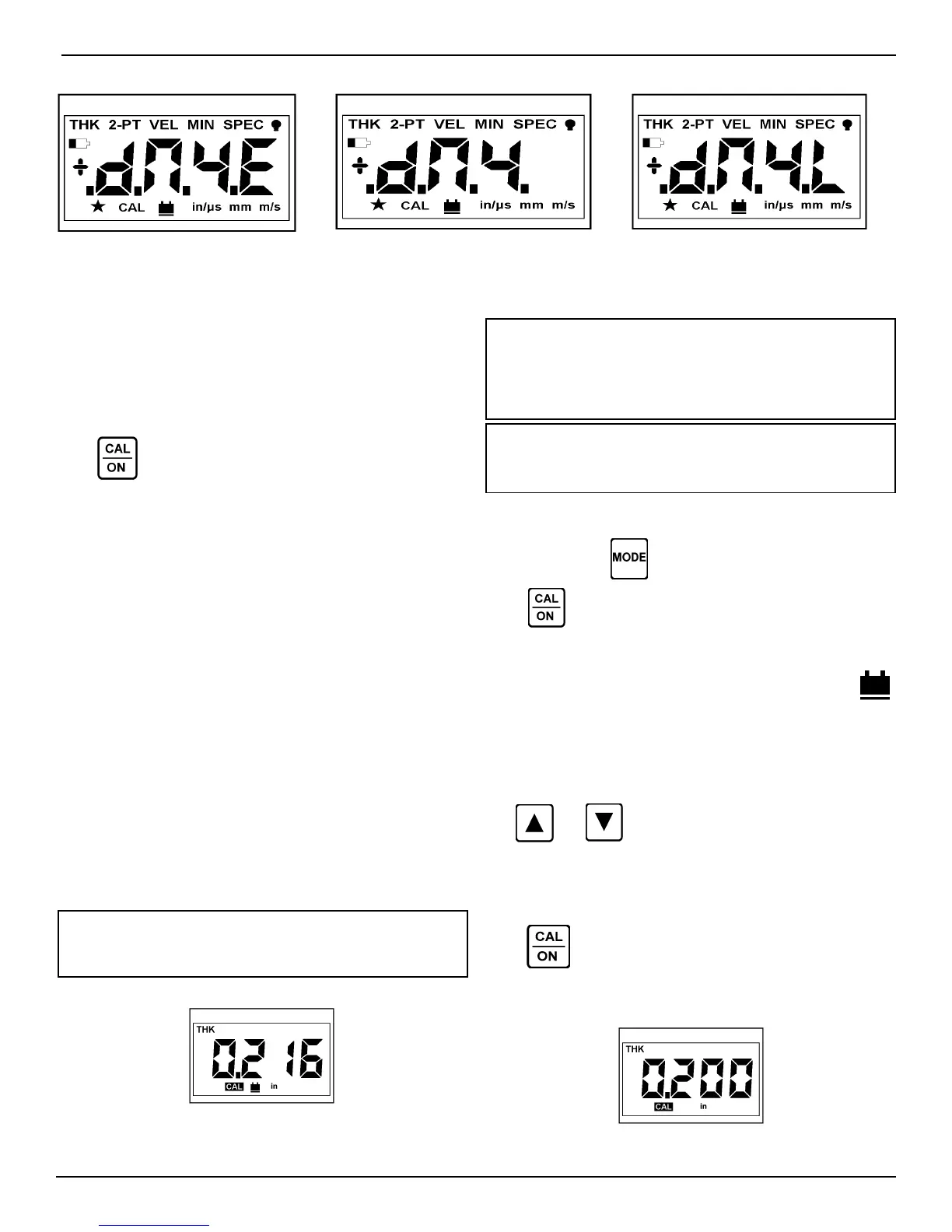
Press
to turn on the instrument. The model and display
annunciators are briefly displayed as shown above, followed by
the current software revision number. Then, the operating mode
and settings from the last session are restored. NOTE: If using
a NON-DIALOG KBA560 Family Probe (i.e. KBA560, KBA560-
WR, KBA560-V) or DA301
Probe, either P560 or P301 may be displayed. If this occurs,
the user must tell the instrument which probe is connected by
toggling with the Up and Down arrow keys to select P560 for a
KBA560 style probe or P301 for the DA301 probe, and press
the CAL/ON key to perform the probe zero procedure and oper-
ate the instrument.
Automatic shut-off occurs after 3 minutes of inactivity.
Coupling probe or pressing a key restarts the timing.
To change the unit of measure or select a different display
resolution setting refer to Section 2.14.
If low light makes the display difficult to read, refer to Section
2.15 for instructions on using the backlight.
Before taking measurements, perform 1-point calibration
(Section 2.5) or 2-point calibration (Section 2.6).
2.0 Operation
2.5 Calibration to a Known Thickness, 1-Point
NOTE:
A calibration standard of the same material and
velocity of sound as the material to be measured is re-
quired . For best results, the thickness of the calibration
standard should be equal to, or slightly greater than the
thickest part to be measured.
NOTE:
Wipe face of probe clean before turning on instru-
ment or connecting probe to instrument for best Automatic
Probe Zero results.
1-point calibration can only be performed if 2-PT mode is
OFF (Section 2.6).
If necessary, press until THK is displayed.
Press
. All symbols and “PO” are briefly displayed. Take
no action until “PO” disappears indicating Automatic Probe
Zero is complete. With CAL flashing, couple the probe to the
calibration standard. Be sure the coupling indicator (
)
lights and the reading is stable, as in Figure 2-3. The dis-
played value may not match the known thickness of the cali-
bration standard at this point. You may keep the probe coupled
or uncouple the probe and wipe the excess couplant from the
probe face.
Use and to adjust the displayed value to match the
thickness of the calibration standard. Scrolling speed accelerates as
the key is held. If a key is released for less than 1 second, scrolling
will resume at the same speed. Figure 2-4 shows how the display
should appear with a 0.200 inch calibration standard.
Press again to end the calibration procedure.
Proceed to Section 2.8 for normal thickness measurement (THK
mode) procedure.
Figure 2-4
Figure 2-3
 Loading...