DM4E, DM4, DM4 DL Operating Manual
Page 12
2.0 Operation
2.8 Normal Thickness Measurement - THK Mode
This procedure applies to parts with ambient surface tempera-
tures. Refer to Section 6.2 for information on taking measure-
ments on hot surfaces.
Be sure that the instrument is on and that the appropriate calibra-
tion procedures in Section 2.5, 2.6, or 2.7 have been completed
for the selected probe type and material to be measured.
If using the alarm feature (DM4 and DM4 DL), make sure the
correct LO and HI limits are set and the alarm is on (Sect. 2.11).
Remove any dirt, loose scale, or flaking from the test surface
and spread a thin layer of couplant on it.
Figure 2-11
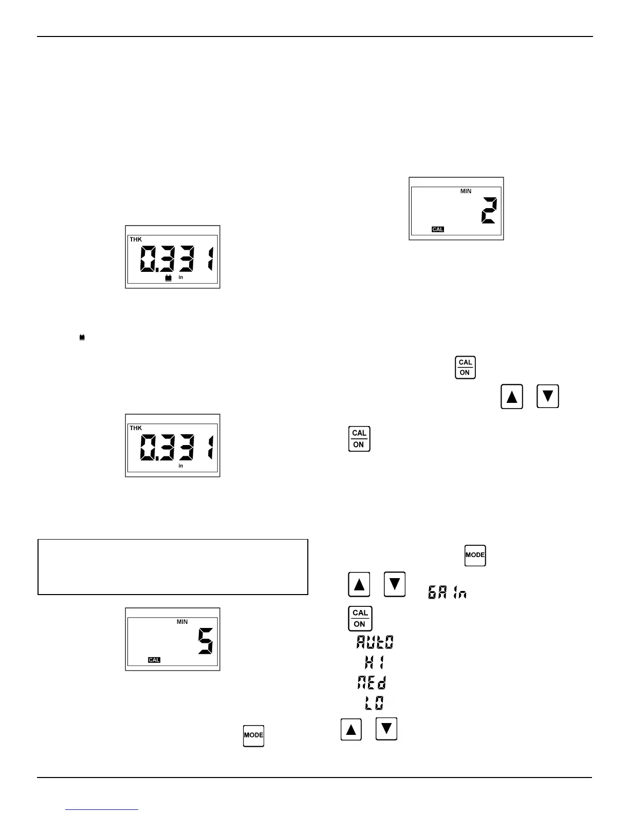
Place the probe gently but firmly on the surface. The coupling
indicator ( ) must light, as in Figure 2-11. Use firm, steady pres-
sure to obtain a stable reading.
The digital thickness reading can be read from the display while
coupled, or the probe can be uncoupled and the last reading will
be held on the display.
Figure 2-12
If incorrect values occur repeatedly, check probe selection
(Sect. 5.2) or contact your Agfa NDT Inc. representative.
Figure 2-14
To end the capture cycle, uncouple the probe for at least the
number of seconds set in the current time-out setting, that is, until
MIN stops flashing. Coupling the probe begins a new minimum
capture cycle.
Setting MIN Time-Out:
The MIN time-out is adjustable from 1 to 5 seconds. With the
instrument in MIN mode, press
to display the current time-
out setting in seconds (Figure 2-13). Use
or to
select a new setting (Figure 2-14).
Press again to activate the new time-out setting and
return to MIN mode for minimum capture measurement
2.10 Receiver Gain Control (DM4, DM4 DL)
The DM4 and DM4 DL have four gain setting options, Automatic,
High, Medium, and Low. The default is Automatic, which auto-
matically selects a gain setting based on the velocity value.
To change the gain setting, press
until SPEC illuminates.
Press
or until appears in the display.
Press
to display current setting:
Automatic gain
High gain
Medium gain
Low gain
Use
or to select a new setting.
NOTE: If a reading is not possible due to low signal caused
by poor coupling or high material attenuation, or if “doubling”
is detected (see page 3), the coupling indicator will not light
and the display will not update.
Figure 2-13
2.9 Minimum Capture Measurement
To enable the minimum capture mode, press
until MIN
illuminates.
MIN mode is used to capture the thinnest value during a series of
readings or rapid sequence of measurements. The measure-
ment updates at high speed to assure detection of thinnest value
during the cycle.
When the probe is uncoupled, the detected minimum is displayed
and MIN flashes to indicate that the time-out sequence has be-
gun. Recoupling the probe while MIN is flashing allows the cap-
ture cycle to continue.
 Loading...