Rev. Date: 12/27/17 Page 9
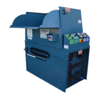
MODEL #1300/2300
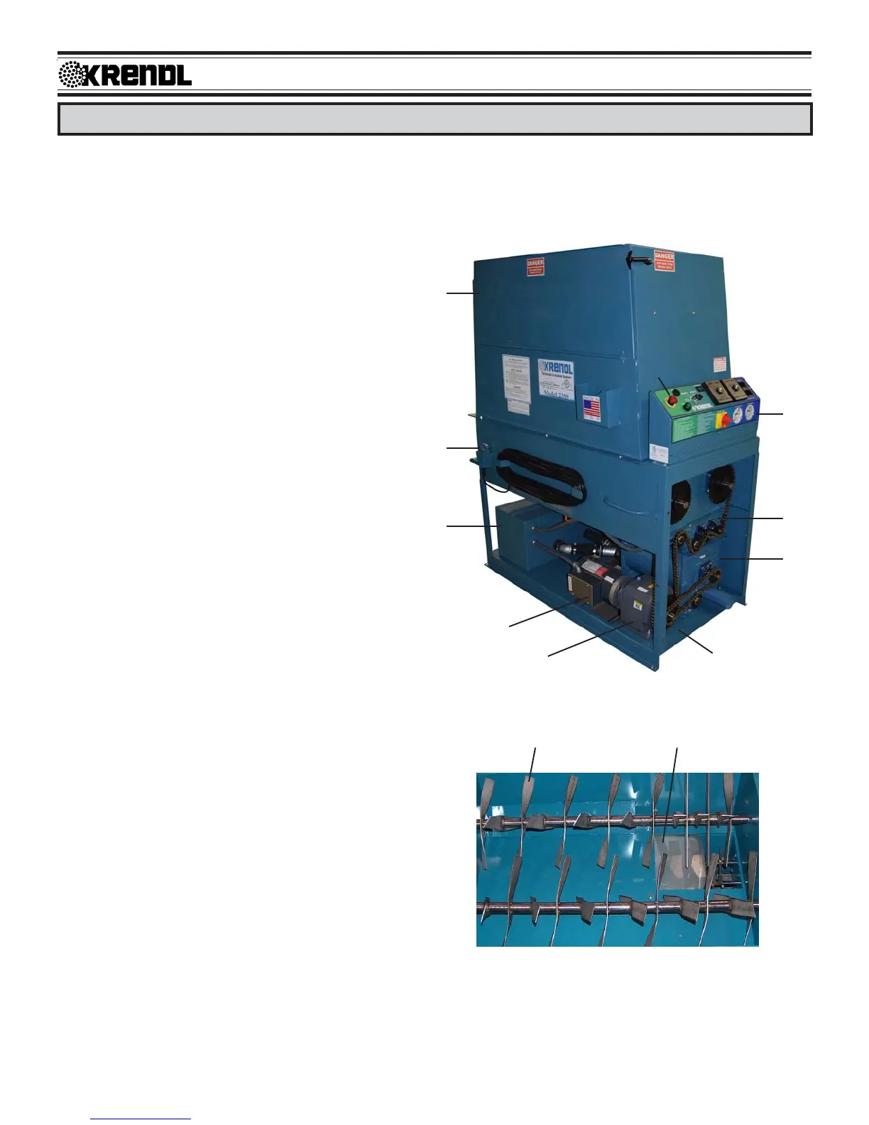
BASIC COMPONENTS
This is a view of the basic components of your machine. It shows the location of each item and gives the
function of each. Use this as a guide throughout the manual.
A) BASE UNIT — Lower frame unit supporting
blower system, speed reducer, motor, airlock
and hopper.
B) AIRLOCK — Traps air and insulation while
providing a metered flow.
C) SLIDEGATE — Meters the amount of insula-
tion dropping into the airlock by controlling
size of airlock opening.
D) SPEED REDUCER — Reduces speed of
agitators/airlock drive motor while output
power remains constant.
E) BLOWER SYSTEM — Unit includes blow-
ers, check valve protection, filter and blower
control.
F) MOTOR — Provides driving power for speed
reducer and agitator/airlock system.
G) AGITATOR — Conditions and augers insula-
tion in the hopper.
H) HOPPER — Upper unit of machine holding
insulation which includes hinged access door.
I) REMOTE CORD HANGER — Storage for
remote control cord.
J) KILL SWITCH — Safety device for immedi-
ate stopping of machine. (Located on electri-
cal box)
K) SHREDDER SYSTEM — Increases
production and coverage on all insulation
products while reducing clumps that may
exist in various insulations.
(L) MAIN CONTROL PANEL — Connects with
main power, allowing operation of unit at ma-
chine or Remote Cord.
(Illustration B)
GC
B
K
L
J
H
I
E
A
F
D