Rev. Date: 12/27/17 Page 21
MODEL #1300/2300
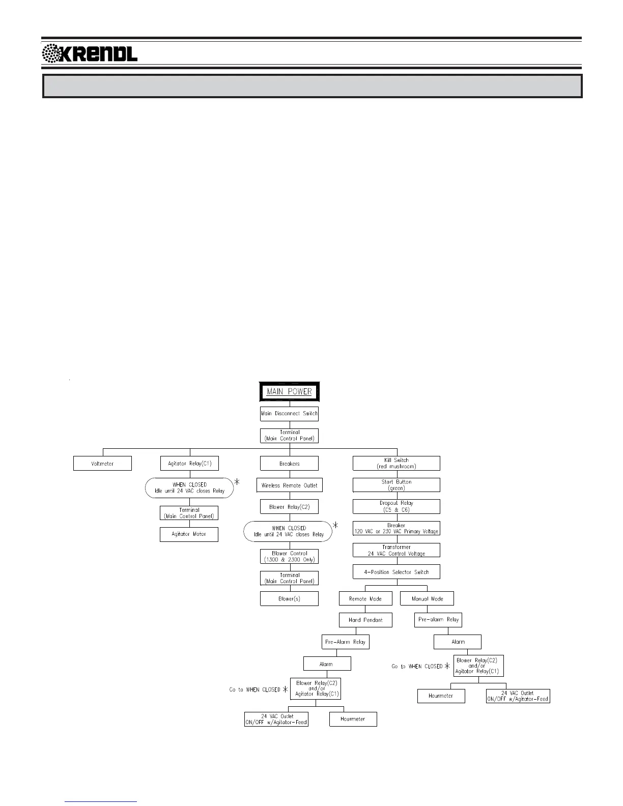
Electrical Flowchart
(Illustration R)
ELECTRICAL SYSTEM
General Operation: (See Illustration R for sequence and Illustration E, S, T, U, V, and W for components) This
unit is powered by one or two separate input sources connected at the bottom of the Main Panel Box. Turning
the Main Disconnect Switch (yellow and red switch located on front of Main Control Panel) to the ON position
distributes power to the Terminal Boards of the Main Control Panel, Voltmeter, Kill Switch, and the Upper
Terminals of the agitator (C1) and the blower (C2) relays. (See illustration E)
When the Kill Switch (red mushroom button) is released (closed) and the green Start Button is pressed, power
is supplied to the dropout relay(s) and the transformer. The transformer supplies 24 VAC to the 4-Position
Selector Switch located on the front of the Main Panel Box.
When the 4-Position Selector Switch is turned to MANUAL mode or the 4-Position Selector Switch is set to
REMOTE mode with remote control hand pendant switch closed, 24 VAC is supplied to the Pre-Alarm relay,
sounding the alarm for a preset time. After the alarm stops, 24 VAC powers the blower (C2) and/or agitator (C1)
relays.
When the agitator (C1) relay is closed, power is also supplied to the 24 VAC ON/OFF Outlet on Main Control
Panel. If power is interrupted to this system by unplugging either main input cord(s), turning Main Disconnect
Switch OFF, or pressing Kill Switch; the green Start Button needs to be pressed to reactivate the system after
power distribution into the system has been reestablished. (See illustrations S, T, U, V, & W for more details.)