Rev. Date: 12/27/17 Page 19
MODEL #1300/2300
(Illustration P)
Double 12.5 AMP (6 Amp 230 volt) 3-Stage Blower
General Maintenance (cont.)
AGITATOR MOTOR:
If agitator motor runs hot, unit may shut off. Wait for motor to cool, then activate the manual reset on motor by
depressing button. (See Illustration O) If unit does not run properly, refer to troubleshooting sections of manual.
The agitator motor should start quickly and run smoothly. If not, shut motor off immediately and check the
cause. Low voltage, incorrect power supply, bad bearings, or misconnected wiring could cause motor failure.
These conditions void the motor warranty. Overload conditions can be detected by checking the electrical
current (amperage) compared with nameplate current (amperage) located on the body of the motor.
AGITATOR MOTOR REPLACEMENT: Disconnect power from unit!!! Unwire motor from Main Control Panel
and remove drive chain. Place a support block under motor to reduce stress while removing four reducer flange
bolts with a 9/16" socket wrench. (If rear bolts are difficult to reach, remove reducer unit from lower frame for
better access.) Pry motor from speed reducer a slight distance, using a large flat blade screwdriver placed in
one of the slots where they join together. Pull motor unit straight away from speed reducer, retaining key. If
motor does not seperate easily, contact factory for assistance. (See Illustration O on page 18) Before installing
replacement motor, refer to motor nameplate. Check connection of new cord for correct voltage (low or high)
and PROPER ROTATION of speed reducer output shaft. Note: Refer to motor nameplate and inter-
change rotation wire leads to obtain counterclockwise rotation on speed reducer output shaft. Rotate
keyways of motor shaft and quill (input) of speed reducer to 12:00 o'clock position. (To turn speed reducer shaft,
remove chain on output of speed reducer.) Assemble the key 3/4" off the end of the motor shaft and coat motor
shaft with anti-seize compound. Align and insert the motor shaft carefully into the input quill. (A flat blade
screwdriver may be helpful to keep key in place as motor shaft is inserted or centerpunch motor shaft.) Secure
to flange with four hex bolts.
Caution: If the motor does not readily seat itself, check to determine if key has moved axially along motor
shaft, causing interference. Tightening motor to reducer with excessive pressure against key will cause
premature bearing failure and overheating of motor and reducer. Connect motor to Main Control Panel and
check for correct rotation of speed reducer output shaft (counterclockwise). Reconnect drive chain
and assemble unit for manual operation.
BLOWER MOTOR:
Periodically remove Blower Filter and vacuum any material that has accumulated inside of blower box and
around blower motor. Blow out any remaining debris around motor and intake orifice of fan with compressed air.
This will extend the life of the blower significantly. Blower Filter life can be extended by occasional removing and
back or reverse blowing through with compressed air. Filter should be replaced periodically depending on use.
If blower produces noise or heat, refer to troubleshooting section of manual.
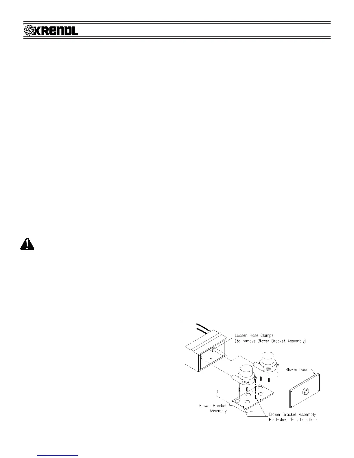
BLOWER REPLACEMENT: Disconnect power from
unit!!! Remove Blower Door. (See Illustration P) Take
note of electrical connections on blower and remove
wire nuts from lead wires. Loosen hose clamp at the
rear of the blower. Remove blower bracket assembly,
secured with bolt, from blower box. Remove three
bolts and spacers from blower bracket and remove
blower. Reverse procedure for assembly. NOTE: DO
NOT OVER TIGHTEN BOLTS ON RE-ASSEMBLY,
IT MAY DAMAGE BLOWERS AND VOID WARRANTY!!
 Loading...