3 ELECTRICAL CONNECTIONS
22
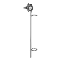
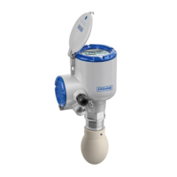
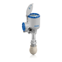
LT40 C/F
www.krohne.com 10/2021 - 4009051601 - AD UKEX LT40 R01 en
3.5 Ex i version of the reed-chain level transmitter
3.5.1 How to connect the electrical cables
Refer to the handbook for data about the device terminals.
Obey the instructions that follow:
• Use the electrical connection procedure in the handbook.
• Put the electrical wires in position and safely attach them to prevent damage. The electrical
wires must also be a sufficient distance from hot surfaces.
• Make sure that unused electrical wires are safely connected to the ground potential of the
hazardous area. If
this is not possible, make sure that each of the unused electrical wires are
safely isolated (other electrical wires, gr
ound etc.) and rated for a test voltage ≥ 500 V rms.
• If it is necessary, make sure the electrical wire insulation gives good protection from
corrosion.
• Connect only to separate certified, intrinsically safe circuits. Make sure that the electrical
circuit characteristics are not more than the values that follow.
• Do not remove more than 6 mm / 0.2¨ of insulation from the wire. Use wire with a minimum
insulation thickness of 0.5 mm / 0.02¨.
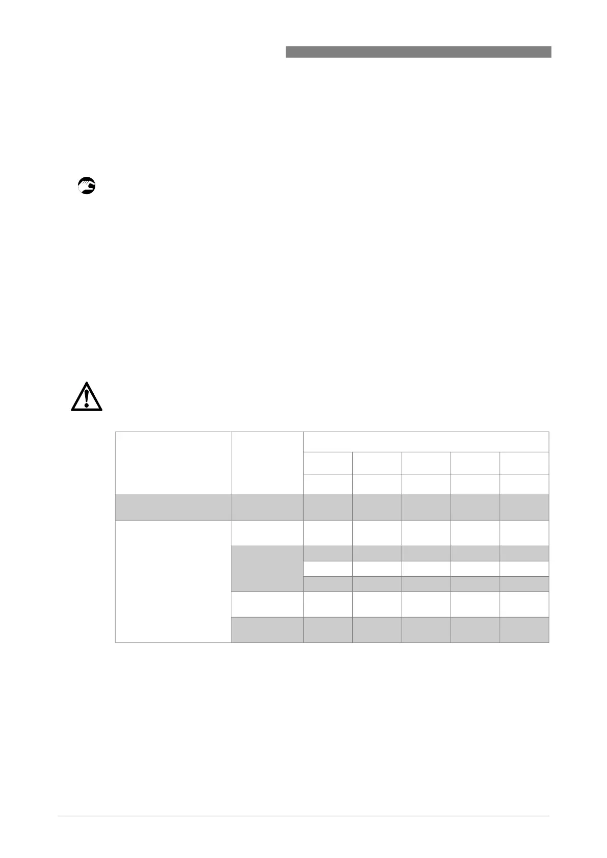
3.5.2 Maximum intrinsically safe values for the electrical circuit
DANGER!
Make sure that the power supply is intrinsically safe.
Output option Configuration Intrinsically safe values for the electrical circuit
U
i
I
i
P
i
C
i
L
i
[V] [mA] [W] [nF] [µH]
4...20 mA
4...20 mA / HART
Barrier
(Ex
ia IIC)
30 100 0.84 23.1 20
FOUNDATION™ fieldbus
PROFIBUS PA
Barrier
(Ex
ia IIC)
30 120 0.84 2 1
FISCO system
(Ex
ia IIC)
17.5 250 2 2 1
15 900 5.32 2 1
Barrier
(Ex
ib IIC)
30 250 5.32 2 1
FISCO system
(Ex
ib IIC)
17.5 Any Any 2 1
 Loading...