ELECTRICAL CONNECTIONS 3
23
LT40 C/F
www.krohne.com10/2021 - 4009051601 - AD UKEX LT40 R01 en
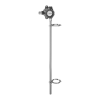
3.6 Ex d version of the reed-chain level transmitter
3.6.1 How to connect the electrical cables
Terminal compartment
• If you connect electrical wires to the terminals in the flameproof compartment, use approved
flameproof cable glands (M20×1.5 or ½ NPT). The cable gland must have an UK-Type
Examination Certificate that agrees with EN 60079-1. Obey the instructions given on the
certificate. Make sure that the tightening capacity of the cable gland is applicable to the
diameter of the electrical wire.
• If you use a conduit to connect electrical wires to the terminals in the flameproof
compartment, obey the instructions that follow. Make sure that the conduit is correctly
attached and the flameproof compartment is sealed. The conduit must have an UK-Type
Examination Certificate that agrees with EN 60079-1. Use conduit stopping boxes that agree
with precautions given in the certificate and data in standards related to the installation of the
conduit.
Obey the instructions that follow:
• The electrical wiring must agree with the applicable standards (e.g. EN 60079-14).
• Use the electrical connection procedure in the handbook.
• Put the electrical wires in position and safely attach them to prevent damage. The electrical
wires must also be a sufficient distance from hot surfaces.
• Make sure that unused electrical wires and shields are safely connected to the ground
potential of the hazardous area. If
this is not possible, make sure that each of the unused
electrical wires are safely isolated (other electrical wires, ground etc.) and rated for a test
voltage ≥ 1500 V
rms.
• Make sure that the device is connected to a PELV (protective extra-low voltage) circuit.
• Make sure that electrical wires are isolated from the ground of the hazardous area.
• If it is necessary, make sure that the electrical wire insulation gives good protection from
corrosion.
• Do not remove more than 6 mm / 0.2¨ of insulation from the wire.
3.7 Electrical data (functional values)
Ouput option LCD display
option
Minimum DC
voltage at I/O
terminals
Maximum DC voltage at I/O
terminals
Ex ia Ex d
[V]
4...20 mA
4...20 mA / HART
Without 10 30 35
With 17
FOUNDATION™ fieldbus
PROFIBUS PA
Without 9 30 32
 Loading...