Installation and Operating Instructions OPTIMASS
96
Zero Problems
• Perform auto zero, observe the displayed value, it should be stable and lower than +/- 0.5%
• If the result is bad:
Stop flow, set 3.1.1 Low flow cut off to 0, 3.1.3 Flow Mode to “+/-”, perform auto zero,
and totalise over 2 minutes. Compare totalised flow to specified zero stability.
For best process results, zero setting should be performed on process fluid at process temperature.
High Zero’s can be caused by: Leaking valves, Air/Gas inclusions, Coating on tube.
Driver or Sensor Coil Fault
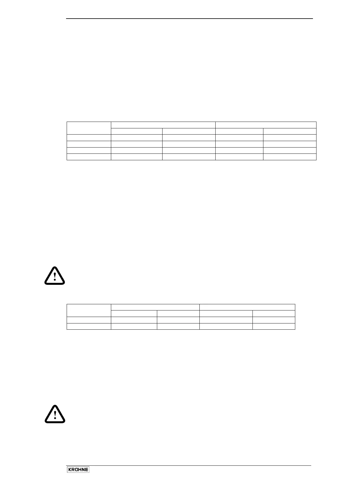
Typical inductance and resistance values:
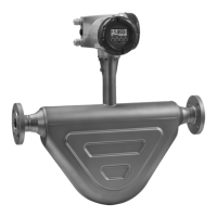
OPTIMASS 7000
Inductance (mH) Resistance (Ohm) OPTIMASS
7000
Driver Sensor A/B Driver Sensor A/B
06/10 5.30 (4.32) 17.32 (10.36) 37 - 42 147 - 152
15 11.7 (8.9) 17.32 (10.36) 47 - 51 147 - 152
25/40 13.1 (11.3) 17.32 (10.36) 40 - 41 147 - 152
50/80 23.5 (12.9) 17.32 (10.36) 49 - 51 147 - 152
• The above data are provided as a rough guide only.
• Damaged magnet coil assembly: Inductance values in brackets.
• Driver = Black and Grey.
• Sensor A = White and Yellow. Sensor B = Green and Purple.
• RTD = Red and Blue (530...550 Ω) at ambient temperature
• Tube strain = Red and Brown:
OPTIMASS 7000 – 06 600 - 800Ω at ambient
OPTIMASS 7000 – 10...80 420 - 560Ω at ambient
• IC strain = Brown and Orange
OPTIMASS 7000 – 06...10 225 - 275 Ω at ambient
OPTIMASS 7000 – 15...80 Not fitted
• Resistance values outside these values could indicate a circuit failuire. Meter may be in start-up or
have measuring errors.
• All circuit should be isolated from ground (meter case) and each other: >20MΩ. If circuits are shorting
to ground, meter may be in start-up.
Caution:
Fluid may be in secondary containment – possible tube failure. Depressurise and safely remove from line
as soon as possible.
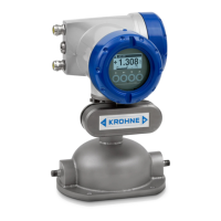
OPTIMASS 3000 (7100)
Inductance (mH) Resistance (Ohm)
OPTIMASS
3000 (7100)
Driver Sensor A/B Driver Sensor A/B
01 1.2 (1.2) 7.2 (7.2)* 54 – 60 105 - 110
03/04 2.6 (8.9) 10.5 (10.36) 43 – 50 132 - 138
• The above data are provided as a rough guide only.
• Damaged magnet coil assembly: Inductance values in brackets.
• Driver = Purple/Black and Orange/Grey.
• Sensor A = White and Yellow. Sensor B = Green and Yellow.
• RTD = Red and Blue (530...550 Ω) at ambient temperature
• Resistance values outside these values could indicate a circuit failure. Meter may be in start-up or have
measuring errors.
• All circuit should be isolated from ground (meter case) and each other: >20MΩ. If circuits are shorting
to ground, meter may be in start-up.
Caution:
Fluid may be in secondary containment – possible tube failure. Depressurise and safely remove from line
as soon as possible.
 Loading...