14
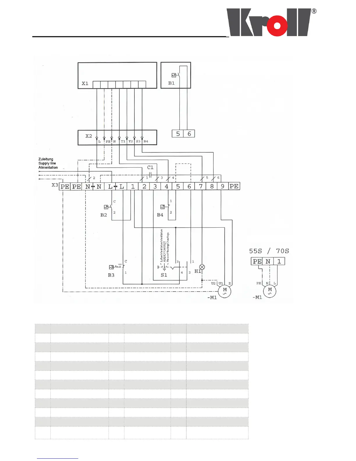
Schaltplan / Circuit diagram / Schéma électrique
25S, 40S, 55S, 70S
Bei Anschluß eines Raumthermo-
states Brücke zwischen
Klemme 5 und 6 entfernen
Remove bridge connector 5 - 6
when room thermostat is connected
Pour raccordement d’un thermostat
d’ambiance enlever le shunt entre
5 et 6
B1 Raumthermostat
(Option)
B1 Room thermostat
(Option)
S1 Thermostat d’ambiance
(Option)
B2 Lüfterthermostat B2 Thermostat fan B2 Thermostat ventilateur
B3
Sicherheitstemperatur-
begrenzer
B3 Overheat thermostat B3 Limiteur de température
B4 Brennerthermostat B4 Burner thermostat B4 Thermostat du brûleur
C1 Motorenkondensator C1 Capacitor for motor C1 Condensateur pour moteur
H1 Störlampe H1 Indicator light H1 Lampe de dérangement
M1 Lüftermotor M1 Fan motor M1 Moteur ventilateur
S1 Wahlschalter S1 Selector switch S1 Commutateur
TK1 Thermokontakt TK1 Thermojunction TK1 Contact
X1 Feuerungsautomatik X1 Burner control X1
Commande automatique
du brûleur
X2 Brennerstecker X2 Burner plug X2 Prise du brûleur
X3 Klemmleiste Schaltgehäuse X3
Connecting strip
Control box
X3
Barre à bornes boîtier
De commande